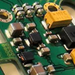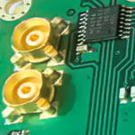
Military High Frequency PCB manufacturing, electronic factory
electronic component distributor company, Flex PCB manufacturing
Computor part supplier, customer: /USA/UK/Canada/South Africa...
radio frequency (RF) circuit board design, Impedance control PCB
-
In modern electronic systems, radio frequency (RF) circuit board design has become increasingly complex and critical. With the rapid advancement of communication technology, from 5G mobile communications to satellite communications and radar systems, the performance of RF circuits directly impacts the quality and reliability of the entire system.
Impedance matching is a fundamental requirement during the design process. RF signal paths must maintain a consistent characteristic impedance, typically 50Ω. Any impedance discontinuity will cause signal reflections, degrading system performance. For microstrip or stripline lines, impedance can be controlled by adjusting line width and dielectric thickness; for differential lines, line spacing also needs to be considered. In practical applications, using an impedance calculator or electromagnetic field simulation software to accurately calculate impedance is essential.
RF Integrated Circuit Architecture, Low-Noise Amplifiers, RF Mixers, Power Amplifiers, RF Oscillators, Phase-Locked Loops
Core Characteristics of Microwave RF Circuit Boards: Microwave RF circuit boards (PCBs) are designed for high-frequency signal transmission (typically 300MHz to 300GHz). Their core characteristics directly determine the performance ceiling of communication systems, radar, satellites, and other equipment. 1. Low-loss transmission of high-frequency signals. Low dielectric loss (Df): Utilizing low-loss dielectrics such as PTFE (polytetrafluoroethylene) and ceramic fillers (such as Rogers RO4000 series), Df values are as low as 0.001-0.003 (common FR4 has a Df of ≈ 0.02), significantly reducing heat loss of signal energy in the substrate. Low conductor loss: Surface treatment processes (such as immersion silver and immersion gold) optimize copper foil roughness (Ra < 0.5μm), suppressing signal attenuation caused by the skin effect.
HDI PCB |
|
HDI digital Rigid PCB Rapid Prototype |
LCD PCB |
|
LCD display PCBA prototype |
Rapid Prototype |
|
High Speed Fr4 Rigid PCB Rapid Prototype China, |
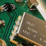
RF PCB |
|
Rogers4003C 4350B PCB fabrication |
Rogers PCB |
|
Rogers Microwave RF PCB manufacturer |
Blind via PCB |
|
High Speed Rogers PCB manufacturing |
Flexible PCB |
|
OLED Flex PCB manufacturer, rapid prototype |
flex pcb |
|
flex connector pcb fabrication, volume and prototype |
FPC |
|
flex FPC PCB manufacturing |
For furhter information, please feel free to contact us, www.pcbsino.com