3G 4G antenna Rogers PCB aplication
China PCB Manufacturing, Shenzhen PCB Manufacturer, Making Circuit boards
PCB Contract manufacturer, PCB Fabrication, Turnkey assembly services
Buy Print circuit board, customer: /USA/UK/Canada/South Africa...
PCB Supplier Shenzhen, China, PCB Manufacturer, Turnkey services
-
PCBSINO is the Top 5 PCB manufacturer company in China.
PCBSINO do rapid Prototype within 24 hours. our rigid PCB like MCPCB and Rogers PCB, FR4, High TG FR4, Rogers 4003, 4350,Al Aluminum metal Core MCPCB, Al2O3 Ceramic,Taconic,Halogen Free material, CEM-3, Fr2, CEM-1, CEM-2, 94VO, Rogers HF material, Polymide, etc.
PCBSINO making many type electronic product for our customer, Our turkey services team can source original components part for your project(Digikey/Mouser/RS...), senior Electronic engineer will follow each step of the production to solve any PCB problem and our team will do final function test in PCB house.
Express PCB |
|
Rigid PCB Rapid Prototype,24 hours |
| Fr4 PCB |
|
prototype Lower to 15USD ! |
| Rapid Prototype |
|
Fr4 Rigid PCB Rapid Prototype China, |
MCPCB |
|
MCPCB Manufacturer China, Shenzhen |
| Aluminum PCB: |
|
Aluminum Metal Core PCB manufacturing, Fabrication |
| Aluminum PCB: |
|
single side, double side MCPCB, 0.5-5mm or more |
Rogers 4350B |
|
Rogers 4350,Rogers 4003 Manufacturing |
| Rogers 4350B |
|
Rogers 4350B,4003C PCB Manufacturer |
| Ro4350B |
|
Rogers High Frequency PCB Manufaturing China |
Turnkey Services |
|
Turnkey PCB Assembly Services, |
| Turnkey services |
|
Print circuit board Manufacturing, Turnkey Services |
| Turnkey Assembly |
|
Through Hole PCB components wave soldering Assembly |
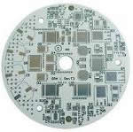
3G 4G antenna Rogers PCB aplication
-
3G 4G antenna Rogers PCB aplication
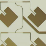
Rogers high frequency pcb widely used in the area of high technologies like communication device,Electronics,Aerospace,Military industry and so on. we have accumulated abandunt experiences in the line of high frequency microwave business for which widely apply to power divider,combiner,power amplifier,line amplifier,base station,RF antena,4G antena etc.
PCB specialties:
PCB types: Rigid PCB/high frequency PCB/high TG PCB and more
PCB materials: FR4/Rogers/halogen-free/PTFE/PPO/PPE and more
PCB finish: HAL/LFHAL/ENIG/immersion tin/OSP
/immersion silver/flash gold/gold plated and more
PCB application: communication/medical/IoT/automobile/system control
/power & energy supply/consumer electronics/LED industry and more
New cars are increasingly equipped with robust crash avoidance technologies. These active safety technologies are enabled by innovative Advanced Driver Assistance Systems using sensor technologies, such as radar, to detect collisions.
Rogers’ Advanced Connectivity Solutions group provides high performance PCB laminates for 24 GHz and 77 GHz automotive radar sensor applications. The RO4000® and RO3000® series materials enable radar sensors to detect upcoming collisions to prevent road accidents. In addition, RO4000® high frequency circuit materials are successfully used in 24 GHz radar sensors for blind spot detection or rear cross traffic alert.
Forward collision warning, emergency brake assist, adaptive cruise control, and traffic jam pilots require radar sensors that operate in the 76-81 GHz range. RO3000® High Frequency Laminates have an excellent Dk tolerance of ± 0.04 and at this high frequency concerns with insertion loss are paramount. These laminates also offer an extremely low dissipation factor, ensuring the dielectric loss component of insertion loss will be very low.
Vehicle to vehicle (V2V) or vehicle to infrastructure (V2I) communications systems send information via dedicated short range at 5.9GHz (DSRC) or intelligent transportation system G5 (ITS-G5) and 3G/4G cellular network. Rogers’ high frequency materials help antenna´s and modules to achieve high performance and reliable connections between cars and infrastructure even at high speed and under harsh vehicle environments.
Power Connectivity and Distribution
As power from a battery is expensive, the challenge is to use the electric power as efficiently as possible. The primary inverter needs to minimize switching losses and maximize thermal efficiency. Auxiliary inverters are used to power vehicle electrification solutions. The range of the vehicle is directly related to the efficiency of these inverters.
Semiconductor-based power systems are able to optimize overall system cost, minimize power losses, increase power density, maximize power savings, extend mileage, and improve battery efficiency.
RO-LINX® busbars from the Power Electronics Solutions group focus on efficient power distribution and lower energy losses, increasing the range of electric vehicles. These laminated busbars provide a customized liaison between the power source and capacitors, resistors, integrated circuits (ICs), integrated gate bipolar transistors (IGBTs), or complete modules.
Within the circuit board, power substrates provide interconnections and cool components. curamik® ceramic substrates are designed to carry higher currents, provide higher voltage isolation, and operate over a wide temperature range.
Benefits for you
100% Tested quality, help you focus on core competencies.
Cutting-edge technology, handle well your special or complicated PCB
Save cost, increase your profitability
Save hassle, save your effort
Save time, upgrade your competitiveness
An excellent team, care what you care
inkjesta tiegħek relatati mal-prodotti tagħna jew prezzijiet se tingħata tweġiba fi 24hrs.
2. istaff sew mħarrġa u b'esperjenza biex twieġeb jistaqsi tiegħek bl-Ingliż fluwenti
3. OEM & ODM, nistgħu ngħinu biex disinn u mqiegħda fis-prodott.
4. Distributorship huma offruti għall disinn uniku tiegħek u xi mudelli attwali tagħna
5. Protezzjoni ta 'żona tal-bejgħ tiegħek, l-ideat ta' disinn u l-informazzjoni kollha privati tiegħek
Termini tal-kummerċ:
1. Il-ħlas: T / T-quddiem (Unjoni tal-Punent, payple hija milqugħa)
2. Il-produzzjoni lead time 100pcs: 5-7days, 500 ~ 1000pcs: 7-10days, fuq 1000pcs 15-20days.
3. Kampjun jistgħu jiġu mqassma fl 3days
4. merkanzija Shipping huma kkwotati taħt talbiet tiegħek
5. port Shipping: Shen Zhen, ċ-Ċina
6. Skontijiet huma offruti bbażati fuq kwantitajiet ordni
7. MOQ: 1pcs
where C is a function of the product of the circuit substrate dielectric constant (Dk) and the area between the signal plane and the ground plane divided by the substrate thickness, or C = (Dk area)/thickness. For thicker substrates, the capacitance decreases and the impedance increases. The lower capacitance is less supportive of the flow of electrons needed for current flow. For thinner substrates or substrates with higher Dk, the capacitance increases and the impedance decreases in support of greater current flow. A wider conductor will increase the area and achieve the same effect.
This relationship for impedance, relating inductance and capacitance, is lossless, with no frequency dependence. To account for the numerous inductances and capacitances of complex circuits, such as differential circuits, a more comprehensive relationship can be used. This relationship is frequency dependent and does include conductor loss and dielectric loss:
Z0 = [(R + jωL)/(G + jωC)]0.5
where
ω = 2πf is the angular frequency;
G is related to dielectric loss; and
R is related to conductor loss.
Inductance and capacitance have opposite effects on a circuit’s impedance. An increase in inductance can cause an increase in impedance, while an increase in capacitance can result in a decrease in impedance. For example, in a 50-Ω system in which impedance variations may reach 45 Ω at one time and 55 Ω at another, the decrease in impedance may be due to an increase in capacitance while the rise in impedance may be the result of an increase in inductance.
The physical characteristics of transmission lines can affect capacitance and impedance, which in turn impact circuit impedance. As conductors are made narrower, the inductance increases and the impedance increases. As conductors are made wider, the capacitance increases and the impedance decreases.
Sudden changes in impedance or differences in impedance are problematic for maintaining high performance in high-speed/high-frequency circuits. Such changes can occur at any transmission-line junction, such as between a coaxial connector and the feed point of a PCB. The change in impedance can cause reflections of RF/microwave signals or high-speed digital signals back to the signal source. This results in less energy delivered to the load as well as with the reflected energy interfering with the propagation of forward energy from the source to the load.
Tracking Transmission Lines
For high-speed/high-frequency circuits, an ideal signal path maintains the same impedance throughout, such as a 50-Ω characteristic impedance, with minimal losses in energy along the path. Most of these signal paths use microstrip, stripline, or GCPW, which may be integrated into complex multilayer circuits. Closed-form equations are available to determine the impedances of these circuit structures, although field-solving techniques typically provide more accurate results.
A closed-form equation to determine the impedance for microstrip, for example, is:
Z0 = [87/(Dk +1.41)0.5 ]{ln[5.98H/(0.8W + T)]}
where
H is the thickness of the dielectric substrate;
W is the width of the transmission line; and
T is the thickness of the transmission-line copper layer.
To ease the calculations, the MWI-2017 impedance-modeling software is available to download for free from the Rogers Corp. Technology Support Hub.
The calculations for finding the impedance of stripline transmission lines are similar to those for microstrip:
Z0 = [60/(Dk)0.5]{ln [1.9B/(0.8W + T)]}
where
B is the thickness of the dielectric substrate from ground plane to ground plane;
T is the thickness of the stripline conductor; and
W is the width of the stripline conductor.
GCPW is a somewhat more complex than microstrip or stripline, with correspondingly more complex closed-form equations for predicting impedance. But again, the free MWI-2017 software provides a quick and straightforward way to perform the calculations based on proven closed-form equations.
Pakkett & Shipping Metodi:
pakkett 1.Vacuum bil-ġell tas-silika, Kaxxa tal-kartun bi ċinturin ippakkjar.
2. DHL, UPS, FedEx, TNT
3. EMS (Normalment għall-klijenti Russja)
4. baħar għal kwantita massa skond il-ħtieġa tal-klijent
Quality practices
Strict PCB requirements complying and modification procedures.
High quality raw materials from Top suppliers for laminates,
copper foil, PP and more
Lean Manufacturing and continuous improvement.
100% E-test, inspections including AOI,
impedance control, soldering ability and more
Humane refund policy
Supporting the military is something RayMing is very proud of, and we were contracted to assemble a PCB for use in a military communications application. The RF PCB assembly used Rogers 4350, Rogers 4003,RT5880 material, and the board required surface mount technology for the double-sided assembly that featured 250 placements. Board specs included 3 layers, standard vias, and 1 panelization. Final measurements came to 8 x 5.75 in. We performed final testing using automated optical inspections and x-ray inspection before delivering product to the customer.
CRC-9 – Used on Huawei modems and Hotspot. (Edit: The MF91 doesn't use CRC-9 connector – Dean – ZTE.)
Note: Whilst the CRC-9 socket is a switching type, it may not always disable all internal antenna(s) on all Huawei modems. Further testing is required (WF).
TS9 – Used on Sierra, ZTE usb modems and Telstra modems, with one exception. See the MF91 above.
Note: The TS9 modem socket switches to disable the internal antenna(s) when the TS9 plug is inserted.
TS5 – Used on the ZTE MF91 Telstra Hotspot. Appears almost exactly the same as the TS9 but is in fact its slightly smaller brother. A TS9 can be plugged into the TS5 but it will not lock into place and fall off easily. The TS5 is a Switching RF connector meaning that when you plug an external connector into the TS5 it will break the connection to the internal antenna. This also means if you damage or tear this RF connector off the PCB then the device is basically unrepairable due to tracks being ripped off the PCB. Please treat the RF ports with care.
SMA – Used on Netcomm (Telstra Home) modems.
Note 1: If you happen to get hold of a commercial modem, it will use RP-SMA connectors.
Note 2: Generally the external antenna socket is used to simply replace the existing modem antenna. It is unlikely to switch.
MS-147 – Used on ZTE, Samsung and Telstra blue tick phones with an external antenna port.
Note: The MS-147 phone socket switches to disable the internal antenna when the MS-147 plug is inserted. Additionally – The MS-147 connector doesn't grab or hold the handset RF port as the MS-147 is a "Cradle" connector designed to be used in car or desk top cradles where the mechanical support is provided by the cradle itself. The patch leads commonly found use a non-standard MS-147 connectors that have been modified to grab / hold the handset RF connector and this leads to increased stress and chance of damage / tearing off of the handset connector. This results in a unrepairable handset in most cases. So please be careful with patch leads.
Serving industries from consumer to military, we continuously strive to build Rogers PCB products that exceed your expectations, to develop long-term customer relationships, and to become your best possible manufacturing partner.
Delivery & logistics
Samples in 1-5 days, volume order in 18days average
24 hours fastest quick turn service
Free samples/sample cost refund policy
Strong packing for long transportation
Best value-added service including shipping, warehousing and more
Late 2010 and 2011 have seen a growing shortage of the mineral Fluorspar - used in the production of not only fluoropolymers such as PTFE but also refrigerants, which are in strong demand for air conditioning systems for the world’s growing middles classes.
This shortage, together with planned and unplanned reductions in PTFE manufacturing capacity, combined with overall robustness of demand, has resulted in both allocations and also significant price increases in PTFE laminates.
The laminate supply chain has taken steps to secure alternative supplies of the component materials that go to make up PTFE laminate and in addition 2011 has seen some new capacity come online.
Whether we shall see further price increases in PTFE-based RF laminates remains to be seen. It is Trackwise’ belief that there is still excess capacity in the world market – resulting in competitive pressures that should resist further price increases.
In addition there are plenty of existing and new RF laminates that are not based upon PTFE and these new products potentially offer an alternative solution. Further PTFE price increases will simply force designers to avoid manufacturing products based on these laminates.
If you are concerned about the potential of price increases of PTFE laminates and wish to discuss a strategy to mitigate this risk, please do not hesitate to contact Trackwise.
f 5G is really going to deliver speeds that are up to 1,000 times faster than the 4G we use today, it needs to utilize the spectrum it will travel over more effectively. Like the journeys to 3G and 4G, the RF path will be critical to the arrival at ‘Destination 5G,’ as will be the need for a high signal to noise ratio (SNR) to ensure a robust data service. This ratio has become increasingly important as the demands for high-speed data increase.
technical parameters:
*npth and pth( 20 um) *thermal stress: 288c/10sec *permitivity: er2.1-10.0
*base copper: 0.5oz, 1oz *together with fr-4 combination *rogers multilayer pcb
*immersion gold *immersion silver, hasl
available substrates:
ro4350b ro4003c tlx-8 (taconic) f4b woven glass-reinforced ptfe
4mil(0.1mm) 8mil (0.203mm) 20mil(0.5mm)
10mil(0.254mm) 12mil(0.3mm) 30mil(0.762mm)
13.3mil(0.338mm) 20mil(0.508mm) 40mil(1.0mm)
20mil (0.508mm) 32mil(0.813mm)
30mil(0.762mm) 60mil(1.524mm)
60mil(1.524mm)
If testing shows you need to improve the signal the best bet is to try to get recommendations from Rogers technical people. I find the Rogers support people helpful and sincere but the coordination between different resource groups could be improved. What has worked for me twice when all-else failed was to send a specific request to Rogers Share a Concern. In your case I think you would want to include your account number, the exact location for your service with a request as to which tower and frequencies Rogers support personnel recommend to improve service. The person who helped me knew the terrain and tree cover for my area. His help was the key for my getting reliable service. Before he helped I was assuming my signal came from a visible tower that does not even serve my area.
New multi-antenna technologies, such as Massive MIMO systems, are considered the most likely candidates to significantly improve spectral efficiency in 5G networks. Implementing MIMO with large-scale antenna arrays, typically with 64 or more transceiver elements, is expected to increase the capacity of a cell well beyond what is achievable today. Large-scale antenna systems become more practical in terms of size at higher frequencies, where the wavelengths become shorter. These antennas are likely to be an important technology in spectrum bands above 2GHz and in TDD spectrum where handset feedback is not needed.
5G will require adding more spectrum while continuing to support previous air-interface technologies and managing multiple frequency bands. Ever more sophisticated RF beamforming and interference mitigation technologies will need to be utilized.
Company culture
People matter most
Humility and discipline
Responsibility and accountability
Honesty and integrity
Maintain excellent work performance
Teamwork and love
s a start you could try the MF275R with the rabbit ear antenna to see if it gets LTE service and then record the signal level and download speed.. Then try your single Wilson antenna in place of one of the rabbit ear antennas and see if the signal level significantly improves and check the download speed. For comparison, you may want to check the download speed at a location with a very good signal, and closer to the tower. That will give you an idea as to the best speed that can be expected. The MF275's battery backup is quite good so it is not a lot of trouble to try it in other locations.
Sufficient stock:
We have sufficient rogers material raw as follow:RO4003C、RO4350B、RO4360、RO4533、RO4535、RO4730、RO4232、RO4233、RO3003、RO3006、RO3010、RO3035、RO3203、RO3206、RO3210、RO3730、RO5780、RO5880、RO6002、RO3202、RO6006,Frequently-used is 4003C,4350B,5880
So we can do pcb circuit board with your detail requirements in the case of you send us gerber files or any other files
For furhter information, please feel free to contact us, www.pcbsino.com