High power rectifier Aluminum mcpcb aplication
China PCB Manufacturing, Shenzhen PCB Manufacturer, Making Circuit boards
PCB Contract manufacturer, PCB Fabrication, Turnkey assembly services
Buy Print circuit board, customer: /USA/UK/Canada/South Africa...
PCB Supplier Shenzhen, China, PCB Manufacturer, Turnkey services
-
PCBSINO is the Top 5 PCB manufacturer company in China.
PCBSINO do rapid Prototype within 24 hours. our rigid PCB like MCPCB and Rogers PCB, FR4, High TG FR4, Rogers 4003, 4350,Al Aluminum metal Core MCPCB, Al2O3 Ceramic,Taconic,Halogen Free material, CEM-3, Fr2, CEM-1, CEM-2, 94VO, Rogers HF material, Polymide, etc.
PCBSINO making many type electronic product for our customer, Our turkey services team can source original components part for your project(Digikey/Mouser/RS...), senior Electronic engineer will follow each step of the production to solve any PCB problem and our team will do final function test in PCB house.
Express PCB |
|
Rigid PCB Rapid Prototype,24 hours |
| Fr4 PCB |
|
prototype Lower to 15USD ! |
| Rapid Prototype |
|
Fr4 Rigid PCB Rapid Prototype China, |
MCPCB |
|
MCPCB Manufacturer China, Shenzhen |
| Aluminum PCB: |
|
Aluminum Metal Core PCB manufacturing, Fabrication |
| Aluminum PCB: |
|
single side, double side MCPCB, 0.5-5mm or more |
Rogers 4350B |
|
Rogers 4350,Rogers 4003 Manufacturing |
| Rogers 4350B |
|
Rogers 4350B,4003C PCB Manufacturer |
| Ro4350B |
|
Rogers High Frequency PCB Manufaturing China |
Turnkey Services |
|
Turnkey PCB Assembly Services, |
| Turnkey services |
|
Print circuit board Manufacturing, Turnkey Services |
| Turnkey Assembly |
|
Through Hole PCB components wave soldering Assembly |
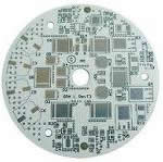
High power rectifier Aluminum mcpcb aplication
-
High power rectifier Aluminum mcpcb aplication
GrandPower Components specializes in high current Diode Bridge Rectifiers, single and Three Phase Diode Bridge Rectifiers. Typical applications for these input rectifier bridges are: welding, generator, battery charger, AC motor drive, and traction markets. Air and water cooled Bridge Rectifier assemblies up to 20,000 amps.
A diode bridge or bridge rectifier is an arrangement of four diodes in a bridge configuration that provides the same polarity of output voltage for either polarity of input voltage. When used in its most common application, for conversion of alternating current (AC) input into direct current (DC) output, it is known as a bridge rectifier. A bridge rectifier provides full-wave rectification from a two-wire AC input, resulting in lower cost and weight as compared to a center-tapped transformer design.
Metal core PCB, MCPCB, is a general term of PCB which traces are made on top of one layer of metal plate for improved heat transferring and dissipating purposes. The most common metals for heat dissipation are aluminum and copper. Aluminum has good heat transfer and dissipation abilities, but yet relatively cheaper. On the other hand, copper has even better performance but relatively more expensive. Therefore, majority of MCPCB are made out of aluminum.
Applications of MCPCB can be categorized into two different types, the industrial and consumer product segments. MCPCB is not a new technique neither a new product. It has been on the market for decades. It was broadly used in high power & high voltage heavy electrical equipments, medical equipments, and military products, even in power supply, rectifier, and transformer. It is a matured technology and product.
MCPCB, Metal Core PCB, thermal PCB - whichever name you prefer, they are all boards which use a base metal material as the heat spreader portion of the circuit board.
Base metals in the MCPCB are used as an alternative to FR4 or CEM3 boards for the ability to dissipate heat away from critical board components and to less crucial areas such as the metal heatsink backing or metallic core.
Metal Core PCB Materials and Thickness
The metal core of the thermal PCB can be aluminum (aluminum core PCB), copper (copper core PCB or a heavy copper PCB) or a mixture of special alloys. The most common is an aluminum core PCB.
The thickness of metal cores in PCB base plates is typically 30 mil - 125 mil, but thicker and thinner plates are possible.
MCPCB copper foil thickness can be 1 - 10 oz.
Advantages of MCPCB
MCPCBs can be advantageous to use for their ability to integrate a dielectric polymer layer with a high thermal conductivity for a lower thermal resistance.
Metal core PCBs transfer heat 8 to 9 times faster than FR4 PCBs. MCPCB laminates dissipate heat, keeping heat generating components cooler which results in increased performance and life.
Metal Core PCB uses - LED Applications and More
High brightness LEDs (HBLEDs) are finding increasing usage in applications like LED lamps, display backlighting, and camera flash for cell phones. A typical high power LED chip has 1mm2 surface area with a total power consumption of 1W. According to the 70-80% power to heat conversion rate in LEDs, the heat flux can be as high as 80 W/cm2. By 2012, the heat flux will reach about 340 W/cm2, which is 6-7 times higher than that of conventional CPU chips [1]. The high heat fluxes at the junction level, coupled with the dense packaging of many components into a small package, results in two thermal management challenges: temperature uniformity across multiple LED junctions and in-plane heat spreading at the heat sink and PCB package levels.
To date, many heat dissipation solutions have been investigated for the thermal management of high-power LEDs, from the chip package level to the printed circuit board (PCB) level to the system level. The package-level thermal management research [1- 5, 11], which involves thermal material research, package design optimization such as 3D packaging design and LED array optimization, and theoretical simulations, is important to determine the packaging thermal resistance of LEDs as well as reduce the footprint. The board-level thermal management research [6-10] is mainly focused on solder material, bonding method improvement, and printed circuit board design optimization. On the system level [4, 12-20], fin-heat sinks with external active cooling is still the mainstream method in industry due to its high reliability and lowest cost. Aside from conventional fans, piezoelectric fans [3, 23] have gained increasing interest from industry. Two-phase passive cooling methods like heat pipes and vapor chambers [15] are becoming good options for emerging HBLEDs. Due to the very high flux heat dissipation requirements, active liquid cooling is widely studied [13-14, 18-19]. Other than active liquid cooling, some novel and advanced methods have also emerged, such as micro-channel coolers [24], electrohydrodynamic approaches [22], and thermoelectric cooling [17]. However, these strategies often involve complex design processes, reliability issues, cost issues, high power consumption, which are the main obstacles for their commercialization and utilization.
In this paper, an advanced high-power LED cooling technology targeted at reducing the thermal resistance on the board level is presented. This technology integrates a passive two-phase thermosyphon into a printed circuit board, which effectively converts the PCB into a high performance heat spreader. Although vapor chamber printed circuit boards and vapor chamber heat sinks have been investigated by other groups [9, 15], the novelty of the current concept is the direct bond between the PCB/heat spreader and LED devices that eliminates extra thermal interfaces as well as the need for electrical insulation between heat sink and PCB. Thus the new design can significantly enhance cooling that allows the LED to run at higher fluxes without degradation in performance, and improve heat spreading that is particularly effective in cooling arrays of high density chips.
2. PASSIVE HEAT SPREADER (PHS) PRINTED CIRCUIT BOARD (PCB)
The thermosyphon is a proven cooling technology with exceptional heat transfer performance. A traditional thermosyphon is a tubular metal structure that consists of an evaporator and a condenser section. A planar thermosyphon can be viewed as a highly efficient heat spreader. When subjected to heating by an electronic device attached to the evaporator, the working fluid inside the thermosyphon vaporizes and thereby limits temperature rise. The vapor condenses back to liquid at the condenser, which is cooled by an external heat sink. In the gravity field, the condensed liquid falls back to the evaporator in the form of a liquid film on the sides of the thermosyphon.
A rectifier used in high-voltage direct current (HVDC) power transmission systems and industrial processing between about 1909 to 1975 is a mercury-arc rectifier or mercury-arc valve. The device is enclosed in a bulbous glass vessel or large metal tub. One electrode, the cathode, is submerged in a pool of liquid mercury at the bottom of the vessel and one or more high purity graphite electrodes, called anodes, are suspended above the pool. There may be several auxiliary electrodes to aid in starting and maintaining the arc. When an electric arc is established between the cathode pool and suspended anodes, a stream of electrons flows from the cathode to the anodes through the ionized mercury, but not the other way (in principle, this is a higher-power counterpart to flame rectification, which uses the same one-way current transmission properties of the plasma naturally present in a flame).
These devices can be used at power levels of hundreds of kilowatts, and may be built to handle one to six phases of AC current. Mercury-arc rectifiers have been replaced by silicon semiconductor rectifiers and high-power thyristor circuits in the mid 1970s. The most powerful mercury-arc rectifiers ever built were installed in the Manitoba Hydro Nelson River Bipole HVDC project, with a combined rating of more than 1 GW and 450 kV.[14][15]
Argon gas electron tube[edit]
Tungar bulbs from 1917, 2 ampere (left) and 6 ampere
The General Electric Tungar rectifier was a mercury vapor (ex.:5B24) or argon (ex.:328) gas-filled electron tube device with a tungsten filament cathode and a carbon button anode. It operated similarly to the thermionic vacuum tube diode, but the gas in the tube ionized during forward conduction, giving it a much lower forward voltage drop so it could rectify lower voltages. It was used for battery chargers and similar applications from the 1920s until lower-cost metal rectifiers, and later semiconductor diodes, supplanted it. These were made up to a few hundred volts and a few amperes rating, and in some sizes strongly resembled an incandescent lamp with an additional electrode.
The 0Z4 was a gas-filled rectifier tube commonly used in vacuum tube car radios in the 1940s and 1950s. It was a conventional full-wave rectifier tube with two anodes and one cathode, but was unique in that it had no filament (thus the "0" in its type number). The electrodes were shaped such that the reverse breakdown voltage was much higher than the forward breakdown voltage. Once the breakdown voltage was exceeded, the 0Z4 switched to a low-resistance state with a forward voltage drop of about 24 V.
Diode vacuum tube (valve)[edit]
Main article: Diode
Vacuum tube diodes
The thermionic vacuum tube diode, originally called the Fleming valve, was invented by John Ambrose Fleming in 1904 as a detector for radio waves in radio receivers, and evolved into a general rectifier. It consisted of an evacuated glass bulb with a filament heated by a separate current, and a metal plate anode. The filament emitted electrons by thermionic emission (the Edison effect), discovered by Thomas Edison in 1884, and a positive voltage on the plate caused a current of electrons through the tube from filament to plate. Since only the filament produced electrons, the tube would only conduct current in one direction, allowing the tube to rectify an alternating current.
Light emitting diode (LED) lighting and LED display require high thermal dissipation performance, low cost LED substrate and long-term reliability. AIT insulated metal substrate laminate is ideal for these Metal Core Printed Circuit Board (MCPCB) applications and are available in high volume and fast delivery at costs that are among the lowest in the industry.
AIT patented (US patent#7,154,046; 6,717,819; 6,580,035; 6,581,276; 6,108,210; 6,297,564; 6,665,193; 6,973,716) insulated metal substrates provide unparalleled thermal and reliability performance. AIT insulated metal substrate differs from traditional Insulated Metal Substrate thermal circuit substrate in the following areas:
LED substrates contain insulated metal for printed circuit boards.
Instead of a thermally conductive rigid fiberglass epoxy laminate, AIT uses a proprietary flexible thermal dielectric insulating layer resulting in stress and warp-free thermal copper-clad laminates with proven low thermal resistance.
Unparalleled thermal conductivity in the insulating layer by eliminating fiberglass fabrics.
High temperature stability to withstand soldering at 300°C.
Multi-layer capability with the same flexible dielectric copper-clad pre-preg that can be laminated at less than 14 psi pressure and at 125°C or higher.
Base metal plates with choice of aluminum and copper from 35 mils to 350 mils.
Thinner insulated metal substrate and pre-preg are available in rolls of 12-inch width.
Thicker insulated metal substrate and pre-preg are available in sheets of 12-inch by 24-inch.
Ideal for power and LED components and modules.
Vacuum diode rectifiers were widely used in power supplies in vacuum tube consumer electronic products, such as phonographs, radios, and televisions, for example the All American Five radio receiver, to provide the high DC plate voltage needed by other vacuum tubes. "Full-wave" versions with two separate plates were popular because they could be used with a center-tapped transformer to make a full-wave rectifier. Vacuum rectifiers were made for very high voltages, such as the high voltage power supply for the cathode ray tube of television receivers, and the kenotron used for power supply in X-ray equipment. However, compared to modern semiconductor diodes, vacuum rectifiers have high internal resistance due to space charge and therefore high voltage drops, causing high power dissipation and low efficiency. They are rarely able to handle currents exceeding 250 mA owing to the limits of plate power dissipation, and cannot be used for low voltage applications, such as battery chargers. Another limitation of the vacuum tube rectifier is that the heater power supply often requires special arrangements to insulate it from the high voltages of the rectifier circuit.
In musical instrument amplification (especially for electric guitars), the slight delay or "sag" between a signal increase (for instance, when a guitar chord is struck hard and fast) and the corresponding increase in output voltage is a notable effect of tube rectification, and results in compression. The choice between tube rectification and diode rectification is a matter of taste; some amplifiers have both and allow the player to choose.
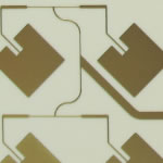
We Buljin design and manufacture aluminum MCPCBs for led light applications as per customers requirement of size and led modal any shape tool punched and v groving facility also available in house. We manufacture MCPCBs (METAL CORE PCB) for high power LED lights applications 1.6mm Aluminium 75 micron dielectric layer and 35 micron copper.
We are leaders in manufacturing Aluminium Base MC-PCBs for all types of High power LED lights. Our MC-PCBs can be used for Down Lights / Spot Lights / Street Lights / Solar Lights / Home Lights / Strip / Cove Lights etc.
We design & Manufacture MCPCBs as per your requirements. We have thousands of design for MC PCBs. We are one stop solution for your requirements in LED lights.
Figure 1(b) illustrates the design concept where the copper lid (at top), PCB and the copper thermal pad (at bottom) form the envelope of the thermosyphon. Compared with the typical surface mount LED in Figure 1(a), the thermosyphon design replaces the low thermally conductive dielectric layer by an enclosed vapor space filled with dielectric fluid. The copper thermal pad of the chip package can be directly soldered to the thermosyphon for minimal interface thermal resistance. It should be pointed out that one PCB thermosyphon heat spreader can have multiple, discrete copper thermal pads to accommodate arrays of LED devices. The dielectric working fluid for the thermosyphon provides the necessary electrical isolation to prevent short circuiting. This feature eliminates the need for a ceramic substrate separating the thermal pad from the electrical circuitry and eliminates the associated thermal resistance. In summary, the technology presented in this paper has the potential of improving thermal performance and simplifying the LED packaging, which will in turn result in cost savings.
Applications that generate a large amount of heat often cannot be adequately cooled using just traditional fans. Conductive cooling through metal core PCBs are an ideal production option.
MCPCBs are most widely found in LED technologies, as they reduce the number of LEDs required to produce a specific illumination. Light emitting diodes release a great amount of heat in applications such as:
Back light unit applications
Street safety applications (streetlights, lighting, etc.)
General lighting applications
System automotive LED applications
Power converters: telecom, industrial, high voltage regulator, power supplies
Hybrid/electric motor control applications
Photovoltaic
Using a metal core PCB in these LED products and applications help to greatly reduce the heat emitted.
Recently, the continuing trend of electronic device miniaturization and introduction of high power LED, MCPCB, with better heat dissipating capability than traditional PCB, is making it even more popular in consumer segments. These new applications are LED backlight, LED lighting, and automotive. The key to success of these applications is determined by the selecting correct high thermal conductivity insulating layer, known as dielectric or PP.
The material used for MCPCB is called Insulated Metal Substrate, IMS. Its structure consist three different materials, on top is the copper foil; in the middle is the PP (or so called dielectric); at the bottom is the metal plate. The most common metal plate used is aluminum or copper.
Nowadays, the hottest consumer application in MCPCB is LED. That’s because the dissipation of heat is getting more attentions to the designer. The reason is because both lifespan and luminous decay of LED are all directly link to junction temperature of LED. Moreover, the led junction temperature is also related to energy consumption. According to experiment conducted by Cree, the time for luminous decay drop to 70% is 100 thousands hours if temperature kept at 65 Celsius. Many tests have proved that LED generates heat is because electricity input cannot completely transform to light but heat. The luminous efficiency of LED is about 100lm/W. The electricity-luminous conversion ratio is only between 20~30%. That means about 70% of current input turn into heat. By reducing heat generated, we can increase luminous efficiency and conserve energy.
For furhter information, please feel free to contact us, www.pcbsino.com