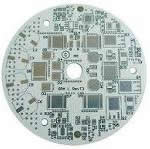
Solid relay Aluminum mcpcb aplication
China PCB Manufacturing, Shenzhen PCB Manufacturer, Making Circuit boards
PCB Contract manufacturer, PCB Fabrication, Turnkey assembly services
Buy Print circuit board, customer: /USA/UK/Canada/South Africa...
PCB Supplier Shenzhen, China, PCB Manufacturer, Turnkey services
-
PCBSINO is the Top 5 PCB manufacturer company in China.
PCBSINO do rapid Prototype within 24 hours. our rigid PCB like MCPCB and Rogers PCB, FR4, High TG FR4, Rogers 4003, 4350,Al Aluminum metal Core MCPCB, Al2O3 Ceramic,Taconic,Halogen Free material, CEM-3, Fr2, CEM-1, CEM-2, 94VO, Rogers HF material, Polymide, etc.
PCBSINO making many type electronic product for our customer, Our turkey services team can source original components part for your project(Digikey/Mouser/RS...), senior Electronic engineer will follow each step of the production to solve any PCB problem and our team will do final function test in PCB house.
Express PCB |
|
Rigid PCB Rapid Prototype,24 hours |
| Fr4 PCB |
|
prototype Lower to 15USD ! |
| Rapid Prototype |
|
Fr4 Rigid PCB Rapid Prototype China, |
MCPCB |
|
MCPCB Manufacturer China, Shenzhen |
| Aluminum PCB: |
|
Aluminum Metal Core PCB manufacturing, Fabrication |
| Aluminum PCB: |
|
single side, double side MCPCB, 0.5-5mm or more |
Rogers 4350B |
|
Rogers 4350,Rogers 4003 Manufacturing |
| Rogers 4350B |
|
Rogers 4350B,4003C PCB Manufacturer |
| Ro4350B |
|
Rogers High Frequency PCB Manufaturing China |
Turnkey Services |
|
Turnkey PCB Assembly Services, |
| Turnkey services |
|
Print circuit board Manufacturing, Turnkey Services |
| Turnkey Assembly |
|
Through Hole PCB components wave soldering Assembly |
Solid relay Aluminum mcpcb aplication
-
Solid relay Aluminum mcpcb aplication
Epec offers thermal clad and metal printed circuit boards with a full selection of high performance or low cost materials from leading suppliers around the world. Thermal clad PCB's are a dielectric metal base with a bonded copper circuit layer. This creates superior heat transfer to help cool components while eliminating problems associated with managing fragile ceramics.
With a wide range of electrical and thermally conductive interface pads, thermally conductive gap fillers, thermal phase change materials and thermally conductive electrically insulating materials, we can manufacture thermal clad & metal backed printed circuit boards that exceed all of our customers' expectations.
Thermal Clad Layers
Thermal clad is a unique layered system comprised of the follow layers.
Circuit Layer:
Printed circuit foil with thickness of 1oz to 5 oz.
Dielectric Layer:
Many different options which offer electrical isolation with minimum thermal resistance. Also used to bond the circuit layer and base material together. Each specific dielectric has its own UL recognition.
Power Conversion: Thermal clad PCB offers a variety of thermal performances, which is highly reliable and compatible with mechanical fasteners
LEDs: Thermal clad PCB assures the lowest possible operating temperatures and maximum brightness, color and life.
Motor Drives: Thermal clad PCB dielectric choices provide the electrical isolation meet operating parameters and safety agency test requirements.
Solid State Relays: Thermal clad PCB offers a very thermally efficient and mechanically robust substrate.
Automotive: The automotive industry uses thermal clad PCB boards as it needs long term reliability under high operating temperatures coupled with its requirement of effective space utilization.
Descriptions:
Thermal clad metal core PCB is a unique layered system comprised of the follow layers:
Base Layer: usually aluminum could also be copper or iron alloy. Thickness from 0.5mm to 4.0mm, standard is 1.5mm
Circuit Layer: Copper foil with thickness of 1oz to 6 oz
Dielectric Layer: a layer of thermal insulation materials with low thermal resistancem
At Opulent, we were always fascinated by the goal of moving up the value chain as far as PCB manufacture is concerned. We therefore decided to focus on Thermal Management innovation in order to cater to the huge global markets. We are proud to be one of the few companies invested time and energy in creating truly reliable thermal solutions with our Metal Clad Printed Circuit Boards (MCPCBs). Our various Intellectual Properties and Patents are a testimony to our efforts in building cutting edge solutions.
First, the characteristics of the aluminum plate
1. The use of surface mount technology (SMT);
2. In the circuit design is very effective for the thermal diffusion process;
3. Reduce product operating temperature, increase power density and reliability, extend the life of the product, the smaller footprint, lower hardware and assembly costs;
5. Replace the fragile ceramic substrates, for better mechanical durability.
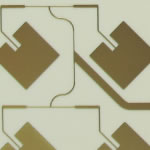
Second, the structure of aluminum plate
Aluminum clad circuit board material is a metal, copper foil, thermal insulation layer and the metal substrate composition, its structure is divided into three layers:
Circuit layer (i.e. line layer): the equivalent of the common PCB laminates, foil thickness loz line to 10oz.
Dielectric layer (i.e. insulation layer): Insulation layer is a layer of thermal insulation materials with low thermal resistance.
Base layer : a metal substrate, usually aluminum or copper can be selected. Aluminum clad and traditional epoxy glass cloth laminated panels.
Circuit layers (i.e. the copper foil) are usually formed after etching printed circuits, so that each member elements interconnected, under normal circumstances, the circuit layer requires a great current carrying capacity, and thus should be thicker foil, thickness 35μm ~ 280μm; thermal insulation layer is aluminum plate where the core technology, it is generally a special polymer made of special ceramic-filled structure, small resistance, viscoelastic performance, thermal aging has the ability to withstand the mechanical and thermal stresses.
High performance aluminum plate using a thermal insulation layer is of such technology, it has very good thermal conductivity and high strength electrical insulation properties; metal substrate is aluminum plate support member, is required to have high thermal conductivity, typically aluminum can also be used copper (including copper can provide better thermal conductivity), suitable for drilling, punching and cutting other conventional machining. PCB material has advantages compared to other materials incomparable. SMT surface mount power components for public art. No radiator, much smaller, excellent heat dissipation, good insulation properties and mechanical properties.
All of the source code are included in this project's download files. They are completely commented.
The code is composed of several components:
A virtual serial port is implemented using the code provided by PJRC . If you need the drivers, go to their site.
I wrote three functions to communicate to the LCD via I2C, then several more functions to initialize the LCD and draw stuff on the LCD. There's also a 8x5 pixel font that is stored in flash memory so I can write text easily to the LCD. (The font is generated by a custom tool I wrote, but you can also find a similar font on Newhaven Display's website)
One file handles the behaviour of the menus, another file handles gathering temperature reading sample, another file is responsible for saving/loading data from EEPROM memory.
The main file handles calculations for temperature control, and automatically going through the reflow soldering stages. It also handles initialization of the various AVR internal hardware like timers.
There are some major details I need to point out here:
When you use "%d" with "printf", the argument is taken as a signed 16 bit integer even if the variable is not, so I wrote "str_from_int" to overcome this limitation. I also wrote "str_from_double" for convenience, as using "%f" doesn't offer much formatting control and "dtostrf" makes the code messy.
The LCD, NHD-C160100DiZ, has a datasheet that says that the maximum I2C clock frequency it can use is 400 KHz. This is false, it will not respond at that frequency and will freeze the I2C bus completely. I've also tried 280 KHz and it still would not work. Finally I used 100 KHz, and it started working.
The LCD's frame rate is ridiculously slow because of my relatively slow microcontroller (running at 8 MHz), the low I2C bus frequency (100 KHz), and the fact that a lot of font data is stored in flash memory instead of RAM.
I'm using PWM to control the solid state relay. My reasoning is that I can control the heating element as if I was controlling the brightness of a LED. The PWM frequency has to be low, for the reasoning behind this, see the appendix.
The PWM value used is ranged between 0 to 65535. So OCR value 0 means 0% duty cycle, OCR value 5000 means 7.6% duty cycle, OCR value 40000 means 61% duty cycle, and OCR value 65535 means 100% duty cycle.
The AD595AQ chip outputs a square wave instead of a constant voltage, the top of the square wave is the voltage that should be read as the temperature. I'm not sure if this is intentional and a part of the AD595AQ's design (I can't figure this out from the datasheet), or if it's my fault somehow. Regardless of the reasoning, the sensor reading routines I wrote accounts for this and will sample only the top of the square waves, it also does averaging.
The raw sensor value is ranged between 0 and 1023 because the ADC on the AVR has 10 bits of resolution. 1023 means the reading is 3.3V because the analog reference voltage is 3.3V. According to the datasheet of the AD595AQ, the output voltage for 320 degrees celcius is 3.227V (0 degree is 0.027 volts, by the way, pretty close to 0, the AD595AQ is supposed to output 10 mV per degree Celcius). From these numbers, I know that 1 degree celcius is 3.125 raw ADC reading units, and 1 raw ADC reading unit is about 0.32 degrees Celcius. These conversion calculations are hard coded into my source code. You should remember the constant of 0.32 when dealing with the log files.
A PID controller is used to calculate the appropriate amount of power to deliver to the heating element. The user is able to edit the PID constants using the user interface.
This PID controller is not a typical PID controller, it is assisted by using information that is already known about the toaster oven's characteristics. You are allowed to input the highest steady temperature that the oven can achieve, and how long it takes to achieve that temperature. From this information, the controller knows how to estimate the correct amount of power to deliver. The PID controller is used to tweak this estimation, which corrects for the non-linearity of the estimation.
Note: Use the "manual PWM control" mode to measure the highest temperature you can achieve and how long it takes to achieve it. Do this by going into that mode from the menu, and turn up the PWM to max, and then save the log reading (or use a stop watch).
There are error checking in the temperature profile and device settings. The software won't allow you to make edits that do not make sense, and if something is wrong, it'll ask you to correct it before continuing.
Refer to the previous "Instructable Step" about the bootloader to see how to compile and bootload the application code, there is even a video in there.
Solid state contactors and relays from DOLD are the first choice everywhere that high switching frequencies and cycles in the industry are needed. They conduct switching and control tasks especially efficiently in numerous applications in industrial and building technology. Their long service life due to wear-free switching is the reason for this. DOLD also has an innovative answer to the problem caused by switching with high load currents, the severe heating of solid state contactors and relays: the use of DCB processes (Direct Copper Bonding) optimises the heat dissipation in the power stage of the device and thus ensure the operational security of your system. Solid state conductors are also used in other applications such as heating, lighting, et cetera.
Third, the use of aluminum plate:
Purpose: Power Hybrid IC (HIC).
1. Audio equipment: input, output amplifier, balanced amplifiers, audio amplifiers, preamplifiers, power amplifiers, etc.
2. Power Supply: switching regulator(DC/AC converter,SW regulator and the like).
3. Communication electronic equipment: high-frequency amplifier circuit transmitters(filtering appliances).
4. Office automation equipment: motor drives.
5. Automotive: Electronic ignition regulator(power controller).
6. Computer: CPU board(floppy disk drive power devices).
7. Power Modules: Inverters(solid relay rectifier bridges).
SSR-40AA-H 40A Solid State Relay Module 80-280V AC / 90-480V AC SSR-40AA
This is solid state relay SSR-40AA-H. 1 x Solid State Relay SSR-40AA-H. Output current: 40A. Fine electro magnetic interference, high sensitivity and fast switching speed. Unique shape and novel structure.
AU $5.26eBay Premium ServiceFree postageFrom China36 sold
AC-AC AC 90-250V to AC 240V 20A Single Phase SSR Solid State Relay With Cover
Solid State Relay Module. Load Current: 20A. Control Current: 2-12mA AC. On-off Time: ≤10mS. Insulation Resistance : 500M ohm/500VAC. We will reply in 24 hours and solve your problem in a friendly way.
AU $6.98From China
Now commonly used in LED lighting to increase longevity, our MCPCBs ensure reliability and play a major role in excellent heat dissipation. Our range of MCPBs is increasingly being recognized as an important energy-efficient component across all sectors including the automotive and power industries.
It is our unique innovations that have earned us respect in the industry. For example, Opulent developed its insulated metal substrates more than eight years ago after recognizing a gap in the market for such a quality product. Reputable LED makers have enrolled Opulent as their long-term Solution Partner.
Power Conversion: Thermal clad PCB offers a variety of thermal performances, which is highly reliable and compatible with mechanical fasteners
LEDs: Thermal clad PCB assures the lowest possible operating temperatures and maximum brightness, color and life.
Motor Drives: Thermal clad PCB dielectric choices provide the electrical isolation meet operating parameters and safety agency test requirements.
Solid State Relays: Thermal clad PCB offers a very thermally efficient and mechanically robust substrate.
Automotive: The automotive industry uses thermal clad PCB boards as it needs long term reliability under high operating temperatures coupled with its requirement of effective space utilization.
Aluminium Base Metal Core PCB Specifications
1 & 2 Layer Dielectrics
Up to 6 oz finished Cu
Aluminum, Copper and iron alloy base material up to .250" thick
HASL, ENIG ,OSP, Pb Free HASL finishing available
Aluminium Base Metal Core PCB Benefits
Lower Operating Temperatures
Increased Power Density
Increased Thermal Efficiency
Reduced Number of Interconnects
Lower Junction Temperatures
Reduced PCB Size
Eliminates Older Hardware
Minimizes Labor Required for Assembly
Wide Variety of Form Factors
Base Layer:
Most often Aluminum, but can also be copper. The most commonly used thickness is 0.040" (1.0mm) although many thicknesses are available.
Thermal Clad and Metal Backed Printed Circuit Boards
For furhter information, please feel free to contact us, www.pcbsino.com