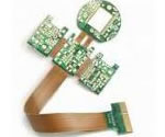
Wired broadband connector Flex PCB application
China Flex PCB Manufacturing, Shenzhen Flex PCB Manufacturer, Making Flex Circuit boards
Flex PCB Contract manufacturer, PCB Fabrication, Turnkey assembly services
Buy Flexible Print circuit board, customer: /USA/UK/Canada/South Africa...
Flex PCB Supplier Shenzhen, China, Flex PCB Manufacturer, Turnkey services
-
PCBSINO is the Top 5 PCB manufacturer company in China.
PCBSINO do rapid Flexible PCB Prototype within. we can make Flexible Print circuit boards and Rigid circuit boards, Flex and Rigid Flex PCB, single side, double side, multilayer Flexible print circuit board
PCBSINO making many type electronic product for our customer, Our turkey services team can source original components part for your project(Digikey/Mouser/RS...), senior Electronic engineer will follow each step of the production to solve any PCB problem and our team will do final function test in PCB house.
Flex PCB |
|
Rigid FlexPCB Rapid Prototype |
| Flex PCB |
|
prototype of Flex PCB |
| Flex Prototype |
|
Rigid-Flex PCB Rapid Prototype China, |
Turnkey Services |
|
Turnkey Flex PCB Assembly Services, |
| PCB assembly |
|
Print circuit board Manufacturing, Turnkey assembly |
| PCBA Assembly |
|
SMT Assembly, EMS/OEM supplier China |
Wired broadband connector Flex PCB application
-
Wired broadband connector Flex PCB application
Nicomatic interconnect solution from discrete wire to flat cable is based on 2 solutions. One is with a FFC crimped with contacts mounted in a housing in a pitch of 2.54mm on one side and a round wire (AWG 28-22) mounted in a housing on the other. Both are connected together and allow an easy replacement of bulky wire cabling parts and thus save weight. The tulip contact shape allows a compatibility with all market standard pin headers with 0.635mm.The other is a mono-housing that allows an easy thin & hybrid non-disengageable connection (AWG 26-22).
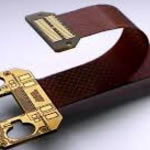
Microflex flexible harness
Microflex™ interconnection is a flat cable harness with screw fixing for high vibration environment. This jumper mates with CMM 220 connector for high mechanical resistance. This solution has been tested to meet MIL-DTL-55302F performances. 3 versions are available Female-Female, solderpin-female and octopus multi branches.
Features:
Board to board, board to wire, wire to wire
From 04 to 60 signal contacts, 2mm pitch
Clear and easy cabling system
weight reduction up to 60% vs round cable
Flexible cable and high life expectancy
Vibration resistance
Mylar technology can be recognized by the presence of solder joints, an amber or dark green color and the presence of a TAB chip bonded to the cable. A heat-sealed connector (HSC) can be recognized by the absence of solder; soft, pliable cable; and black, green and yellow coloring. (See Figure 1 below.)
All Mylar cable technology can be repaired, reworked and replaced with a soldering iron, wire solder and solder paste, or a bonding unit. HSC technology is divided into three groups, each having a different criterion for repair, and it can only be replaced with a process bonding unit. For factory-bonded results, HSC material requires the application of controlled pressure and specific temperature for a precise time.
HSC technology Heat-sealed connectors are not soldered materials but, rather, a flexible substrate with conductive traces attached. The joint created by bonding (electrically and mechanically attaching) the connecting end of the HSC-type flex cable is the heat-sealed connector. The conducting traces, or "wires," are filled with conductive particulate material. This technology was developed to provide a quick and easy, but still reliable, method to connect an LCD to a printed circuit board. Telecommunications devices such as pagers, cellphones and two-way radios use this technology extensively. It is not necessary to understand the precise mechanics of the technology to replace or repair devices that incorporate HSC material. However, a technician will be more comfortable knowing why a repair or replacement is successful instead of only knowing how to perform the replacement.
Information about conductive epoxy and polymer technology, and specifications, is not readily available to the community of engineers working in the PCB environment, but understanding the physical properties and limitations is sufficient for successful repairs.
A good analogy is to think of the flex (ribbon) connector as a flat wire harness with each wire replaced by a bead of conductive epoxy. Visualizing this bead of conductive epoxy as being similar to a bead of caulking compound filled with metal particles will help illustrate the reasons for various time, pressure and temperature profiles that are required for different types of HSC material.
Temperature, time and pressure cause the conductive material to become plastic and make a mechanical, as well as an electrical, connection to the circuit card pad area. Different types of material require different profiles. Each type of HSC material has different metal particles in various amounts and sizes. Some materials require higher temperatures than others to change from a rigid to a plastic state. The pressure requirement relates to forcing the particles to make contiguous contact to ensure conductivity.
Three main types of HSC materials are in current use for telecommunications. Each type has its own mechanical and electrical characteristics that are unique and provide a range of price-performance features that can be applied to various products. The pitches, the spacing and size of the trace are different as well, as shown in Figure 2 below. Understanding the properties of the three types of HSC materials provides guidance for the repair of various products, as well as an appreciation of their use, removal and replacement limitations.
Monosotropic - Used for fine pitches, monosotropic material can be recognized by its diminutive traces. If you can hardly see it, it is monosotropic. This material can be made to a pitch as fine as 0.22mm. The material contains gold and nickel particles and has a low contact resistance. Its yellow color denotes the titanium dioxide used in the manufacturing process when coating the connector with Thermoset adhesive. Monosotropic materials are used in Motorola Memo Express alphanumeric pagers, for example.
Anisotropic - The lowest-cost material to yield reliable bonded joints, anisotropic material is filled with gold-plated nickel particles, and it is used in most pagers. Anisotropic material is also being used to manufacture replacement parts for planar materials used in pager technology. Anisotropic material can be produced in pitches as fine as 0.29mm, but for such a fine pitch, monosotropic material is usually used. The material's color is green-and-white or black-and-white. Anisotropic materials are used in Bravo Express pagers.
Planar - The original pager connective material, planar is limited to pitches of 0.3mm or larger. It is more expensive than the other two types and contains no metal particles. Planar material is yellow with black traces that are usually easy to see. Planar materials are found in Bravo Alpha pagers.
Traditional voice calls are predominantly two party calls, requiring a point-to-point connection using only the voice medium. To access pictorial information in a remote database would require a point-to-point connection that sends low bit-rate queries to the database and high bit-rate video from the database. Entertainment video applications are largely point-to-multi-point connections, requiring one-way communication of full motion video and audio from the program source to the viewers. Video teleconferencing involves connections among many parties, communicating voice, video, as well as data. Offering future services thus requires flexible management of the connection and media requests of a multi-point, multi-media communication call.[3][4]
Multi-rate[edit]
A multi-rate service network is one which flexibly allocates transmission capacity to connections. A multi-media network has to support a broad range of bit-rates demanded by connections, not only because there are many communication media, but also because a communication medium may be encoded by algorithms with different bit-rates. For example, audio signals can be encoded with bit-rates ranging from less than 1 kbit/s to hundreds of kbit/s, using different encoding algorithms with a wide range of complexity and quality of audio reproduction. Similarly, full motion video signals may be encoded with bit-rates ranging from less than 1 Mbit/s to hundreds of Mbit/s. Thus a network transporting both video and audio signals may have to integrate traffic with a very broad range of bit-rates.[3][5]
A single network for multiple services[edit]
Traditional networks[edit]
Traditionally, the various services mentioned above were carried via separate networks: voice on the telephone network, data on computer networks such as local area networks, video teleconferencing on private corporate networks, and television on broadcast radio or cable networks and.
These networks were largely engineered for a specific application and are not suited to other applications. For example, the traditional telephone network is too noisy and inefficient for bursty data communication. On the other hand, data networks which store and forward messages using computers had limited connectivity, usually did not have sufficient bandwidth for digitised voice and video signals, and suffer from unacceptable delays for the real-time signals. Television networks using radio or cables were largely broadcast networks with minimum switching facilities.[2][3]
1: Advancements in MCAD-ECAD Co-Design – Ensuring All ECAD Data are Exchanged Seamlessly to Reduce Iterations
Speaker: Vince Di Lello, Cadence
Consumer IoT and Industrial IoT are increasing the number of flex and rigid-flex designs in the industry. At the same time, complexity of designing flex and rigid-flex designs is increasing as improvements are made in the manufacturing process. Since many of the flex and rigid-flex designs have to fit into tight enclosures with imaginative and impressive ways to bend and fold the flex portion, it is important to ensure the details of flex and rigid-flex designs are passed accurately and efficiently between the ECAD and MCAD teams. What if your design tool made the communication between those two worlds more efficient? Using accurate and detailed STEP models, including enclosures from the MCAD team, mechanical intent, including transformation of the flex sections, can now be articulated and physical conflict issues resolved directly from within the ECAD tool. This presentation will demonstrate how your design tool can assist in overcoming issues, as well as save time and iterations by bringing system-level 3D MCAD views and checks directly to the PCB designer’s desktop
Indoor wireless positioning has long been hampered by technologies that were not designed for this purpose, such as Bluetooth, Wi-Fi and assisted GPS. UWB is a low-power digital wireless technology that offers significant increases in location precision and range while transmitting large amounts of digital data short distances over a wide spectrum of frequency bands. UWB’s low-power requirements offer increased battery life of sensors and tags, leading to reduction in overall operational costs.
Taoglas’ range of UWB antennas, designed in Taoglas’ Munich, Germany, engineering center, features both state-of-the-art flexible and rigid PCB embedded UWB antennas as well as UWB embedded SMT chip antennas. The flexible FXUWB range of antennas were developed utilizing a simple “peel and stick” assembly process, attaching securely to non-metal surfaces via 3M adhesive, with a highly flexible micro-coaxial cable mounting. There is also a version in a rigid PCB format, if desired. The UWB chip antennas are designed to be surface mounted directly onto a PCB. Both series of antennas help designers future-proof devices, keeping costs low while covering all common UWB commercial bands.
Today's report is nothing we haven't heard before. KGI Securities analyst Ming-Chi Kuo has said for months that he expects the iPhone 8 will be hard to come by until early 2018, and we've heard several rumors pointing towards problems with the display lamination process and other high-tech components like the 3D sensor embedded at the front of the device. The Wall Street Journal points to OLED assembly as a major reason for the delays.
Apple and its suppliers also ran into trouble manufacturing the OLED displays. The display modules are being produced in Vietnam by an affiliate of Samsung Electronics. Unlike the OLED display module in Samsung's own smartphones, in which the display and touch panel are integrated, iPhone's display module has the touch panel outside of the display, according to a person familiar with the technology.
INSEAD
INSEAD is a graduate business school with campuses in Europe, Asia and the Middle East. INSEAD, widely considered one of the best business schools in the world, allows its students to study in the US (West Coast- San Francisco via Wharton exchange, East Coast- Philadelphia via Wharton exchange, Midwest- Evanston near Chicago via Kellogg exchange), in Asia (Singapore via INSEAD Asia Campus exchange and Shanghai via CEIBS exchange), in the Middle East (Abu Dhabi via INSEAD Middle East Camp... + Show more
Law Degree
University of Michigan - School of Law
The University of Michigan, founded in 1817, celebrates a long and distinguished history. It was in 1787 that the Northwest Territorial Ordinance provided public land for this and other Midwestern universities and established a tradition of respect for excellence in higher education. Three Native American nations—the Ojibwa (Chippewa), Odawa (Ottawa), and Bodewadini (Potawatomi)—subsequently granted
Figure 12 Chicken wire sections stitched together to form the TASH element. Figure 14 Complete HF through VHF TASH antenna ready for operation. simulation data for return loss and SWR of the measured data with the simulated data shown in Figure 5. On air tests were performed using an old ICOM IC-720A transceiver with no antenna tuner. The tests were performed on the bands shown in Table 1. Full 100 W output was not obtained above 20 MHz due to the transceiver SWR fold-back circuits. Minor antenna adjustments or a simple tuner could easily reduce the SWR to allow full power from the IC-720A. Since the SWR was less than 2:1 on the five bands, newer transceivers could probably handle the SWR without a tuner. Figure 13 The complete TASH antenna on its side showing the feed point. a layer of chicken wire was stapled to the 2 4 frame to form a counterpoise for the TASH antenna element. Then the TASH element was wrapped on the framework spaced about 2 inches above the counterpoise chicken wire. The coaxial feed and element shorts locations are shown in Figure 6. Figure 13 shows the feed point with the antenna on its side. The complete HF TASH antenna is shown is Figure 14. HF TASH Test Results The return loss of the HF TASH antenna was measured using an HP 8754 Network Analyzer. Figure 15 shows the measurements with return loss and SWR scales overlaid. Note the similarity in the Conclusions The amateur radio community has several assigned bands at various frequencies in the 2 to 30 MHz range. Unfortunately, they are spaced several megahertz apart, so that few antennas can cover all bands of interest. A TASH antenna can be an excellent choice for situations requiring multi-band operation. The wide bandwidth of the TASH antenna would even allow operation on the VHF bands from the same HF antenna. One of the best features of the TASH antenna is its dc to ground impedance at the antenna input. It s a short circuit to the counterpoise, which makes it inherently short circuited at frequencies below the lower frequency cutoff. This can reduce the occurrence of intermodulation products from broadcast, appliance hash, and other sources of low frequency noise. The short can also protect the rig from lighting damage and charge build up (a problem with cone and discone antennas), but a slight modification to the antenna might be necessary if lightning protection is a real concern. The distance between the antenna connection center conductor and the outer return is approximately 20 feet. Measured dc input imped- QEX July/August
1.
Higgins H, Radio Frequency Technology and In-Body Communications Systems, BSN 2005 Conference Proceedings.
Google Scholar
2.
Yang G-Z, Body Sensor Networks, Springer 2006, pp 117–143.
Google Scholar
3.
MICS Band, Australian Communications Agency, Paper SP 6/03, 2003.
Google Scholar
4.
ETSI EN 301 839-1 v1.1.1, 2002-4. “Electromagnetic Compatibility and Radio Spectrum Matters (ERM); Radio Equipment In the Frequency Range 402 to 405MHz for Ultra Low Power Medical Implants and Accessories; Part 1; Technical Characteristics, Including Electromagnetic Compatibility Requirements and Test Methods”. Page 42.
Google Scholar
5.
Wojclk J et.al.; “Tissue Recipe Calibration Requirements, SSI/DRBTP-D01-003”. Spectrum Sciences Institute RF Dosemetry Research Board, 51 Spectrum Way, Nepean, Ontario, K2R 1E6, Canada.
The iPhone manufacturing process requires more steps and more layers of adhesive and protective film than are involved in Samsung's manufacturing process, the person familiar with the process said, creating a greater risk of manufacturing error.
Apple also wanted to add Touch ID to the display of the new device, but it "proved difficult," leading Apple to abandon the fingerprint sensor and lose valuable time as deadlines loomed.
While we hear rumors of supply shortages each and every year, it's worth noting that this year's rumors are both more concrete and more dire. If Kuo's predictions are correct, many of us hoping to get our hands on a new device could be waiting for weeks or months as Apple works to ramp up production.
Extended shortages may also impact Apple's holiday sales period, which is often the company's strongest, but because there's also a new iPhone 7s and 7s Plus on the horizon, it's difficult to determine the effect extended iPhone 8 shortages might have on the company's Q4 bottom line.
Customers hoping to get an iPhone 8 as soon as possible will want to pre-order the device right when it goes on sale. It's not entirely clear yet if the iPhone 8 will be available shortly after being introduced on September 12 or if the supply issues will lead Apple to delay shipments beyond September.
“Today’s emerging applications require very precise indoor localization of assets, objects and people,” said Ronan Quinlan, co-CEO, Taoglas. “UWB can work as a type of ‘indoor GPS’ to help solve the precision dilemma for indoor applications, bringing much greater levels of precision than current technologies. We optimize complex antenna performance parameters such as the Group Delay, Polarization and Fidelity Factor. Taoglas’ first-to-market line of UWB antennas are designed to help our customers capitalize on this need for real-time precision localization, with the quality, reliability and flexibility they’ve come to expect from working with Taoglas. One particular antenna we co-developed exclusively with DecaWave is the UWCCP.01 circularly polarized chip antenna, the first mass-market antenna specifically designed to enable a new generation of autonomous applications.”
The UWB antennas were designed for use with the DecaWave DW1000 chip, and are also compatible with any other UWB sensor modules on the market. Since its launch in December 2013, more than 3.5 units of the DW1000 have shipped across multiple industries. From real-time location of people and assets in factories, hospitals and mines, to automotive keyless entry systems, to drones, connected home and sports, the accurate location and secure communications capability of the DW1000 has already taken numerous applications to new heights.
Who should attend: PCB Designers, System Designers, Hardware Engineers, Fabricator Engineers/Operators, Assembly Engineers/Operators, Test Engineers
Course rating (Beginner, Intermediate, Advanced): Beginner
View Specs
Printed Circuit Board (PCB) Fabrication Services -
Supplier: IMET Corporation
Description: From small-scale to large-scale, IMET Corporation's in-house manufacturing offers you the flexibility of a turnkey manufacturing solution without the large quantity minimums often required by contract manufacturers. We've set up our facilities are set up to assemble printed circuit boards and
Location: North America, United States Only, Northeast US Only
PCB Type: Single-Sided Boards, Double-Sided Boards, Multi-Layer Boards, Flexible Boards, Rigid-Flexible Boards, SMT Components, THT Components
Supplier Capability: PCB Design / Layout, Prototype Quantities, Production Quantities, Testing and Evaluation, PCB Assembly
2: Intelligent DfM
Speaker: Kevin Webb, Mentor Graphics
Design for Manufacturing (DfM) applications have been around for a while and have helped many companies reduce product costs, improve quality and get products to market faster. PCB technology and manufacturing processes have become more complex and varied, however, making it difficult to create a simple set of DfM rules. In this session we will discuss a new approach to implementing DfM analysis. DfM applications today must be able to make intelligent decisions for the user about what DfM checks are relevant for their PCB materials and technology, all while considering the manufacturing processes to be used in the production. Those applications achieving this objective will serve their users better and make the benefits of DfM attainable by a larger audience.
Who should attend: Assembly Engineers/Operators
Course rating (Beginner, Intermediate, Advanced): Beginner, Intermediate
Benefits of a single network for multiple services[edit]
It was desirable to have a single network for providing all these communication services to achieve the economy of sharing. This economy motivates the general idea of an integrated services network. Integration avoids the need for many overlaying networks, which complicates network management and reduces flexibility in the introduction and evolution of services. This integration was made possible with advances in broadband technologies and high-speed information processing of the 1990s.[2][3]
Fiber optics for broadband networks and MSO[edit]
While multiple network structures were capable of supporting broadband services, an ever-increasing percentage of broadband and MSO providers opted for fibre-optic network structures to support both present and future bandwidth requirements.[6]
CATV (cable television), HDTV (high definition television), VoIP (voice over internet protocol), and broadband internet are some of the most common applications now being supported by fibre optic networks, in some cases directly to the home (FTTh – Fibre To The Home). These types of fibre optic networks incorporate a wide variety of products to support and distribute the signal from the central office to an optic node, and ultimately to the subscriber (end-user).
Bonding (establishing a mechanical and electrical connection) of these materials requires temperature, pressure and time As shown in Figure 3 above, each of the three materials has different bonding requirements. There is an operating time, temperature and pressure envelope for each type of material.
When replacing an HSC connection, note the properties of the material used. When bonding a monosotropic material, for example, if an anisotropic pressure of 70psi is applied, then the bonded joint will look fine, but it will not have a proper mechanical connection to the pad. The joint may even work for a short time_then fail when the device is dropped or undergoes an ambient temperature change. If an anisotropic material is bonded at a monosotropic temperature, the insulating material between the conductive traces could melt and short. If a planar material is bonded at the high end of the monosotropic pressure envelope, then the bonding head could cut the material.
If the HSC cable is peeled away from the circuit card, then the residual conductive material on the pad areas of the PCB will reveal the way a properly bonded joint appears after bonding, as shown in Figure 4 at the left.
The SOLO series 9258 is a one-piece connector used to connect two PCBs in a cost effective manner. This connector is a 1.0mm pitch available in an 8 position with stack heights of 0.40mm and 0.80mm. It is available with or without location bosses. This connector is designed for PCB surface mounting and is supplied in tape and reel packaging. Gold plated pads on the mating PCB or suitable flex circuits provide connection between the boards.
General features:
The Benefits of Inkjet Wire Marking
Jan 30, 2013 | The Benefits of Inkjet Wire Marking Inline Wire and Cable Identification By Pete Doyon , VP of Product Management , Schleuniger , Inc . Page 1 of 6 1 / 30 / 2013 Introduction Many OEM’s require that individual wires and cables used in their products be clearly identified with a mark or label . For some , such as in the military and aerospace markets , wire and cable identification ( or “ wire ID ” ) is mandatory and the process is governed by stringent specifications , such as SAE AS50881 ( formerly MIL5088L ) . For others , the decision to use wire ID is a voluntary one . Wires and cables can be identified as part of an “ inline
Peregrine Semiconductor
Peregrine Semiconductor
A leading fabless provider of high-performance, radio frequency integrated circuits, or RFICs.
San Diego, California, USA
Manufacturer of Components
NSOP Reduction for QFN RFIC Packages
The MTP40S is an extremely small and light pocket transmitter with selectable 10mW/50mW/100mW options and a built-in limiter designed for professional wireless microphone applications. Its OLED display, dedicated buttons, and joggle selector make it quick and easy to use. The MTP40S benefits from the latest Wisycom RF technology along with enhanced robustness against noise and intermodulation.
CONSUMER ALERT: Most users do not need a license to operate this wireless microphone system. Nevertheless, operating this microphone system without a license is subject to certain restrictions: the system may not cause harmful interference; it must operate at a low power level (not in excess of 50 milliwatts); and it has no protection from interference received from any other device. Purchasers should also be aware that the FCC is currently evaluating use of wireless microphone systems, and these rules are subject to change. For more information, call the FCC at 1-888-CALL-FCC (TTY: 1-888-TELL-FCC) or visit the FCC’s
Aug 31, 2017 | Wire bonded packages using conventional copper leadframe have been used in industry for quite some time. The growth of portable and wireless products is driving the miniaturization of packages resulting in the development of many types of thin form factor packages and cost effective assembly processes. Proper optimization of wire bond parameters and machine settings are essential for good yields. Wire bond process can generate a variety of defects such as lifted bond, cracked metallization, poor intermetallic etc. NSOP – non-stick on pad is a defect in wire bonding which can affect front end assembly yields. In this condition, the imprint of the bond is left on the bond pad without the wire being attached. NSOP failures are costly as the entire device is rejected if there is one such failure on any bond pad. The paper presents some of the failure modes observed and the efforts to address NSOP
Easy mating from discrete wire to flat cable in a 2.54mm pitch
Full compatibility with CrimpFlex™
Housings from 2 to 12 ways for 1SM/2SL & from 1 to 20 ways for DFM
Weight reduction to -30% vs. round wires
Multi-point connection from flex to PCB
Recyclable & RoHS tool (P/N 14841) with instruction
Male and female crimp contacts provided in bulk or in reel
For furhter information, please feel free to contact us, www.pcbsino.com