High insulation Al2O3 Ceramic PCB aplication
China PCB Manufacturing, Shenzhen PCB Manufacturer, Making Circuit boards
PCB Contract manufacturer, PCB Fabrication, Turnkey assembly services
Buy Print circuit board, customer: /USA/UK/Canada/South Africa...
PCB Supplier Shenzhen, China, PCB Manufacturer, Turnkey services
-
PCBSINO is the Top 5 PCB manufacturer company in China.
PCBSINO do rapid Prototype within 24 hours. our rigid PCB like MCPCB and Rogers PCB, FR4, High TG FR4, Rogers 4003, 4350,Al Aluminum metal Core MCPCB, Al2O3 Ceramic,Taconic,Halogen Free material, CEM-3, Fr2, CEM-1, CEM-2, 94VO, Rogers HF material, Polymide, etc.
PCBSINO making many type electronic product for our customer, Our turkey services team can source original components part for your project(Digikey/Mouser/RS...), senior Electronic engineer will follow each step of the production to solve any PCB problem and our team will do final function test in PCB house.
Express PCB |
|
Rigid PCB Rapid Prototype,24 hours |
| Fr4 PCB |
|
prototype Lower to 15USD ! |
| Rapid Prototype |
|
Fr4 Rigid PCB Rapid Prototype China, |
MCPCB |
|
MCPCB Manufacturer China, Shenzhen |
| Aluminum PCB: |
|
Aluminum Metal Core PCB manufacturing, Fabrication |
| Aluminum PCB: |
|
single side, double side MCPCB, 0.5-5mm or more |
Rogers 4350B |
|
Rogers 4350,Rogers 4003 Manufacturing |
| Rogers 4350B |
|
Rogers 4350B,4003C PCB Manufacturer |
| Ro4350B |
|
Rogers High Frequency PCB Manufaturing China |
Turnkey Services |
|
Turnkey PCB Assembly Services, |
| Turnkey services |
|
Print circuit board Manufacturing, Turnkey Services |
| Turnkey Assembly |
|
Through Hole PCB components wave soldering Assembly |
High insulation Al2O3 Ceramic PCB aplication
-
High insulation Al2O3 Ceramic PCB aplication
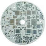
Product Name: copper clad ceramic substrate, 100x100 ceramic insulator, alumina ceramic circuit board, one side clad plate
Material: Al2O3: 95% SiO2: 1.28% CaCO3: 3.25% other: 0.47% firing temperature: 1580 degrees
Hardness: > 1100 HV5 compressive strength: 25000 kgf/cm2 volume resistivity: > 1012 insulation failure strength: 18 Kv/mm dielectric constant: 9.5
Plane degree: 1.5mm; > substrate thickness: 1.0mm surface: copper clad
1 of Enlarge image
LEDs suffer heat problems, which understandably can limit their success as a light source. Much attention is given to the heat sink, but less to the layers and barriers between LEDs and the heat dissipating surface.
A change of concept and material allows for significant gains in thermal management and reliability, as well as a simplified system. Using ceramics as heat sink, circuit carrier, and part of the product design needs some fresh thinking and the willingness to overcome traditional patterns. A simulation process based on Computational Fluid Dynamics supports thermal optimisation and technical product design. So let’s explain the theoretical approach, the proof of concept, and what and how improvement with ceramic heat sinks can be achieved.
LEDs are known to be efficient and are loved for being tiny. But they are only really tiny as long as heat management is not involved. Incandescent light sources work with temperatures up to 2,500°C; LEDs are much colder and many people stumble upon the fact that heat is such an issue. Being relatively cold, LEDs still do produce heat which is not yet a problem. But they are based on semiconductors which, roughly speaking, simply allow temperatures below 100°C.
According to the law of energy conservation, the thermal energy must be transferred to the surrounding area. The LED can only use a small temperature gap between 100°C of the hot spot and 25°C ambience temperature; offering just 75 Kelvin. Consequently a larger surface and powerful thermal management are needed.
TWO OPTIMISATION BLOCKS
Let’s take a look at the LED in Figure 1. Here Group 1 is the LED itself and mainly remains untouchable. Its centre is a die and a heat slug, a copper part, which connects the die with the bottom of the LED. Thermally, the ideal solution is direct bonding of the die to the heat sink itself. Due to mass production this concept is commercially unrealistic. We consider the LED as a standardised “catalogue” product which can not be modified. It is a black box.
Group 2 is the heat sink, transmitting energy from a heat source to a heat drain. This is usually the surrounding air either with free or forced convection. The less aesthetic the material, the higher is the need to hide it. The more you hide it the less efficient is the cooling. Alternatively, pleasing and worthy materials can be used, directly exposed to the air and being part of the visible product design.
In-between group one and two is Group 3 providing mechanical connection, electrical isolation, and thermal transmittance. That seems contradictory since most materials with good thermal conductivity conduct electricity as well. Vice versa, almost every electrical isolation material translates into a thermal barrier. The best compromise is soldering the LED to a PCB which is glued on the metal heat sink. The original function of a PCB as a circuit board can be kept. Although PCBs exist with various thermal conductivities, they remain an obstacle to thermal transfer.
RTT FOR VALID SYSTEM COMPARISON
The thermal resistance of LEDs (die to heat slug pad) and heat sinks is available from the manufacturer. But there is little focus on group 3 and its significant influence on the total thermal performance. Adding all thermal resistances but the LED (group 1), the total thermal resistance Rtt (Fig. 2) is born. The Rtt allows a real comparison of heat.
CERAMICS: TWO JOBS IN ONE MATERIAL
It is common to optimise only the heat sink. Hundreds of designs are available, essentially of aluminium. But for further improvement it is necessary to advance or even eliminate the third group. Electrical isolation has to come from the heat sink itself by the use of other materials. Our conclusion is ceramic. Ceramics, e.g. Rubalit (Al2O3) or Alunit (AlN), combine two crucial characteristics: they are electrically isolating and thermally conductive.
Rubalit has a lower, Alunit a slightly higher conductivity than aluminium. On the other hand Rubalit is less expensive than Alunit (Fig. 3). Their thermal expansion coefficient is adapted to semiconductors, they are rigid, corrosion-resistant, and RoHS compliant. Completely inert, they are the last part of a system to die. The simplified construction (without glues, insulation layers, etc.) combined with a direct and permanent bond between the high-power LED and the ceramic heat sink create ideal operating conditions for the entire assembly. Put simply, what isn’t there won’t wear out and materials that expand in proportion to each other won’t separate. The result is excellent long-term stability, secure thermal management, and exceptional reliability. A patent has been filed and the concept has been named CeramCool.
THE THEORY
The ceramic heat sink CeramCool is an effective combination of circuit board and heat sink for the reliable cooling of thermally sensitive components and circuits. It enables the direct and permanent connection of components. Also, ceramic is electrically insulating per se and can provide bonding surfaces by using metallisation pads. Customer-specific conductor track structures, even three-dimensional ones, can be provided if required. For power electronic applications direct copper bonding is possible. The heat sink becomes a module substrate that can be densely populated with LEDs and other components. It quickly dissipates the generated heat without creating any barriers.
VALIDATION AND PROOF OF CONCEPT
The idea to use ceramics was first cross-checked in several simulation models. To predict thermal behaviour of various designs a method based on Computational Fluid Dynamics (CFD) was developed. Equally, an optimised ceramic heat sink for 4W cooling was developed. Manufacturing requirements where taken into account. The optimised geometry allows operation of a 4W LED at a maximum temperature below 60°C which was validated against physical tests. The design is square in shape (38mm x 38mm x 24mm) and comprises longer, thinner fins with a larger spacing. The identical geometry in aluminium with a PCB mounted LED showed significant higher temperatures. Depending on the thermal conductivity of the PCB (from λ = 4 W/mK to λ = 1,5 W/mK), the temperature raised between 6 to 28K.
Already a 6K reduction at the hot-spot implies significantly less stress for the LED. The total thermal resistance of the Rubalit assembly is at least 13% better than aluminium with identical shape. Using Alunit the minimum improvement of CeramCool reaches 31%. These good results are outperformed largely for both ceramics if the heat drop of 28K is taken into account.
FLEXIBILITY OF CONCEPT
The concept is flexible and can be used for different targets. It’s your choice whether you run an LED on its optimum temperature assuring high life time and high lumen per Watt or you accept higher temperatures reducing life time and efficiency. A temperature spread from 50°C to 110°C is common. If more lumina are needed, the 4W-heat sink can be equipped with 5W or 6W LEDs. Splitting the power into several 1W LEDs helps to get better heat spreading (Fig. 4). The results are 65°C with 5W and 70°C with 6W.
SMALLER SIZES
With the chip permanently and reliably bonded to the electrically insulating CeramCool, the heat sink takes more heat and becomes hotter. It takes the burden off the LED and does exactly what it is made to do, namely, cool the critical components. The reduced die temperature allows a downsized surface and a smaller heat sink. Its higher temperature makes it possible.
COOLING WATER AT 2MM DISTANCE
Air cooling reaches its limits at very high power densities. This is where liquid cooling is best suited. One example is CeramCool water cooling which benefits from the inertness of ceramics. No corrosion can cause trouble. The concept follows the same goal as for air cooled heat sinks: shortest (thermal) distance between heat source and heat drain. With ceramic it is feasible that the cooling water is only 2mm away from the LED heat slug. No other concept can do this in combination with the durable nature of ceramics. Multilateral electrical circuits can be printed directly on the ceramic without creating thermal barriers.
SIMULATION MODELS FOR CUSTOMISED SOLUTIONS
Since most of the applications where CeramCool is used are customer-specific solutions, it is essential that the performance can be proved before the first expensive prototypes are made. Intensive studies were made to build up simulation models. These simulation models have been verified against various tests and showed reliable correlations to test results. Based on this knowledge, new concepts or variations are easily evaluated.
RETROFIT LAMPS AND ISOLATION
The problem of retrofit lamps is mainly one of isolation. Any retrofit lamp has to be class II construction because you cannot guarantee an electrical earth. This means that any exposed metal part has to be isolated from mains wiring by double or reinforced insulation. Often retrofits with metal heat sinks do not comply, as it requires larger distances (like 6mm in air) or double layers of insulation which stop the heat sink from working well. The integrated electronic driver in a GU10 LED is so restricted for space that this is a very complex product. With a ceramic heat sink, even if the driver fails completely mains electricity is not conducted by the heat sink and the product is safe.
The new CeramCool GU10 LED spot works with any LED. Socket and reflector are made from a single material: a high-performance ceramic. Thus it has simple class II construction with safe insulation. A high voltage 4W LED only reaches a maximum temperature below 60°C, so both lifetime and light output are increased. In all CeramCool heat sinks the substrate becomes the heat sink. Here it acts as the lamp, or even the luminaire. The simplified design delivers extremely high reliability. In addition, the mount and reflector of GU10 LED spots are usually made of different materials. With this solution, far fewer materials are used and ceramics are exploited for their electrical insulation, good EMC, and high mechanical and chemical stability.
SUBMOUNTS FOR IMPROVING EXISTING LED SYSTEMS
Ceramics can greatly improve both new and existing LED systems. Using a ceramic CeramCool submount, the PCB between LEDs and metallic heat sink can be replaced with ease, considerably reducing the total thermal resistance Rtt of the system. This offers important advantages such as very good thermal conductivity while delivering perfect electrical insulation and high temperature stability. Whether submount or complete circuit board—ceramic is absolutely corrosion resistant, which eliminates galvanic corrosion especially outside.
CONCEPTS UNDER DEVELOPMENT
High power applications, especially for outdoor usage, gain as well from the features of CeramCool. A family of round heat sinks, which will meet the demands of different power levels, is under development. The concept combines cost efficient production with high flexibility of usage. It is going to be a “semi customised” product family.
Tensky ceramic PCB is made up of innovative, research and development engineers the configuration, the target is the first leader professional Ceramic base plate, ceramic circuit board brought to workshop, using a semiconductor membrane technology for a customer with OEM/ODM service, Resolution, Customer in electronic circuit in various thermal heating, high pressure, and the problem.
Main materials:Al2O3 and AlN substrate.
Image layers metal:Ti, TiW, Cu , Ni, Pd , Au , Ag, AuSn, Sn, Al…and other metallize。
Primary market:high-power LED stand, cooling, optical communication components, optical power solar energy base plate, vehicle with electrical, air, and the electronic circuit board roadbed, and so on.
The special is high power LED market context, such as 1515, 2016, 3535, 5050, 6060, 1215 substrate, and LED - COB integrated stand, practices, as well as UVLED stand, etc. product is the Secretary's main work specifications, provide customer professional views, reduced customer test and failure risk.
APEC 2013, the Applied Power Electronics Conference, is the leading event for practical and applied power electronics engineering in North America. It is scheduled for March 17-21 at the Long Beach Convention Center, California. Rogers Power Electronics Solutions Division, consisting of Power Distribution Systems (PDS) and curamik®, will feature its high-performance power electronics products in booth # 405.
Rogers PDS Division will demonstrate the benefits of their industry-standard RO-LINX® series of laminated busbars, known for their reliability, safety, and durability in the most demanding applications. RO-LINX® busbars provide engineers with UL listed solutions for a variety of applications, including mass transit and electric propulsion, industrial drives, renewable energy, medical devices and data centers.
In addition, the PDS Division will showcase its two latest additions to the established RO-LINX series: The RO-LINX PowerCircuit® Solutions and the RO-LINX® Hybrid.
RO-LINX PowerCircuit Solutions are the ideal alternative when the current and power requirements of the application exceed the capabilities of a standard PCB solution. Its compact 3D design and superior thermal management result in space and weight savings. RO-LINX PowerCircuit Solutions are highly integrated structures that are solder-process compatible. These products help engineers design power circuitry with the smallest possible footprint.
RO-LINX PowerCircuit Solutions are ideal for a wide range of power distribution applications in electric vehicles/hybrid-electric vehicles (EV/HEVs), wind/solar power, and variable frequency drives (VFD).
The RO-LINX Hybrid busbar is especially designed to reduce installation time of a battery module by combining power and signal lines for voltage and temperature measurement, in a one piece solution. Integrated surface mount components, such as connectors, enhance the functionality of the assembly. The RO-LINX Hybrid is the ideal solution in battery management systems for (Hybrid) Electric Vehicles.
Aside from their standard product offering of Al2O3 and AlN DBC (direct-bond-copper), curamik will present the new members of their product family, Si3N4 (silicon nitride) DBC and AMB (active metal brazing) ceramic substrates. Additionally, their unique micro-channel cooler solutions will also be on display.
curamik ceramic substrates, based on a ceramic isolator, Al2O3 (alumina), AlN (aluminium nitride), or Si3N4 (silicon nitride), are known for great thermal conductivity. Their high heat capacity and heat spreading make curamik’s products irreplaceable in power electronics. Target applications are power modules in the Industrial, Automotive, Renewable Energy, and Mass Transit sectors as well as cooling of diode laser and high performance computing applications.
Specification:OEM/ODM
Size:OEM/ODM
Introduction:Ceramic circuit board has a resistance to high voltage, high current, fast heat dissipation, high thermal
Ceramic circuit board has a resistance to high voltage, high current, fast heat dissipation, high thermal stability characteristics, such as the semiconductor industry, optical industry and mainframe devices, fiber-pass design, high-frequency communications, LED industry, solar industry, IC packaging, car electronic circuits, electronic circuit applications such as military maturing and growth.
Introduction:
This section ceramic circuit board design concept is a dedicated supply LED module plant, can be directly packaged
chips directly Wire bonding brighter and longer life on the system board, because the ceramic heat with excellent
results, but also allow your LED
METALLISATION AND COMPONENT PART CARRIER
To fully exploit the optimisation potential we have to look at metallisation possibilities as well. Ceramic can be coated directly with proven thick-layer technologies with its high adhesion force (WNi(Au), Ag, AgPd, Au, DCB, AMB) or thin film processes with its smooth surfaces (allowing precise light angles). A finish for better soldering can be obtained using electroless nickel or gold (immersion or cathodic deposition). The possibility of metallisation makes the whole surface of the heat sink useable as a circuit carrier which can be firmly packed with LEDs and drivers on customised circuit layouts, while providing reliable electrical insulation. The process can be simplified by bonding the chip directly onto the specially designed metallic surface.
ASSEMBLING AND QUALITY CHECK
Just a quick glance on how the assembling can be done. One potential assembler is BMK, a well-known German centre for electronic services. They do prototyping as well as series production. The heat sinks are mechanically set in a production framework and a solder cream is automatically applied, which is pressed through a template. In the next step LEDs and other components are mounted onto the heat sinks followed by subsequent processing in reflow ovens. A durable bond is established after cooling. The soldering points and position of the components are visually inspected, followed by a 100% functional test. Only now is the product complete and ready to be sent to the customer.
high efficient and high performance raymond grinding mill for quartz limestone etc.
hsm professional lifetiem warranty export ghana placer gold mining equipment
hot sale mining processing equipment portable jaw crushers for sale
high quality crushing process of coal handling plant with ce iso
hot selling aggregates crushing machine with high quality
high quality ball mill for sale uk with large capacity and low price
hot selling 150t h sand washing line made in china
hot sale vibrating screens for stone crusher price
hospital laundry equipment isolated type washing machine best quality washer
high quality mobile crushing plant with capacity of 10 300tph
hsm professional lifetiem warranty jigger beneficiation production plant
high reliability crushed dolomite equipment mini crusher plant for stone crushing
able 1: Symbol VCEO IC ICM Quick reference data Parameter collector-emitter voltage collector current peak collector current single pulse; 1 ms Conditions open base Min Typ Max 100 200 Unit V mA
Table 2: Pin Pinning Description emitter TR1 base TR2 collector TR2 emitter TR2 base TR1 collector TR1
Table 3: Ordering information Package Name PMBTA42DS SC-74 Description plastic surface mounted package (TSOP6); 6 leads Version SOT457 Type number
Table 4: Marking codes Marking code P4 Type number PMBTA42DS
Table 5: Limiting values In accordance with the Absolute Maximum Rating System (IEC 60134). Symbol VCBO VCEO VEBO IC ICM IBM Ptot Parameter collector-base voltage collector-emitter voltage emitter-base voltage collector current peak collector current peak base current total power dissipation single pulse; 1 ms single pulse; 1 ms Tamb 25 °C
Conditions open emitter open base open collector
© Koninklijke Philips Electronics N.V. 2006. All rights reserved.
Table 5: Limiting values...continued In accordance with the Absolute Maximum Rating System (IEC 60134). Symbol Per device Ptot total power dissipation Tamb 25 °C
junction temperature ambient temperature storage temperature
Device mounted an FR4 Printed-Circuit Board (PCB), single-sided copper, tin-plated and standard footprint. Device mounted an FR4 PCB, single-sided copper, tin-plated, mounting pad for collector 1 cm2. Device mounted on a ceramic PCB, Al2O3, standard footprint.
In automotive PCB field, powertrain holds the largest proportion, about 32% for the time being, including mainly Engine Control Unit, Starter, Alternator, Transmission Control, Fuel Injection, and Power Steering. For xEV, complexity, high voltage, high current and high temperature of Inverter and Converter pose extremely high requirements on PCB.
Powertrain seizes over 50 percent, followed by Body with about 25 percent (primarily Lighting, HVAC, Power Door & Seat, Keyless, and TPMS). LED lighting, which enjoys a high share, is highly demanding on PCB, usually adopting MCPCB (Metal Core PCB). Thirdly, Safety systems, consisting mainly of ADAS, ABS, and Airbag, make up about 22%. The last is Cockpit systems, mainly covering Instrument Display and Infotainment.
Automotive PCB has exceedingly high requirement on reliability, creating the biggest threshold. Recall system in automobile industry requires makers to take risks of faulty products. As small makers cannot afford this, they are usually ruled out. Challenges for automotive PCB include reliability, high temperature, high frequency, and high current.
PCBs in automotive engine and gearbox need to withstand high temperature above 150℃, so ceramic substrates must be used, for ceramic multi-layer substrate contains mainly alumina (Al2O3) and aluminum nitride (AlN). High temperature co-fired ceramic (HTCC) PCB is usually sintered at temperature of over 1600℃, and the conductor is high-melting point tungsten or molybdenum, which can be sintered together at the same time.
Japanese Murata puts forward low temperature co-fired ceramic (LTCC), which finds few applications. Ceramic substrates are mostly supplied by Japanese KYOCERA and U.S. Rogers. PCBs used by European and U.S. carmakers are largely provided by German Schweizer, Duwel, and Wurth, and U.S. TTM. Japanese carmakers are mainly served by CMK and Meiko.
A change of concept and material allows for significant gains in thermal management and reliability, as well as a simplified system. Using ceramics as heat sink, circuit carrier, and part of the product design needs some fresh thinking and the willingness to overcome traditional patterns. A simulation process based on Computational Fluid Dynamics supports thermal optimisation and technical product design. So let’s explain the theoretical approach, the proof of concept, and what and how improvement with ceramic heat sinks can be achieved.
1 of Enlarge image
LEDs suffer heat problems, which understandably can limit their success as a light source. Much attention is given to the heat sink, but less to the layers and barriers between LEDs and the heat dissipating surface.
A change of concept and material allows for significant gains in thermal management and reliability, as well as a simplified system. Using ceramics as heat sink, circuit carrier, and part of the product design needs some fresh thinking and the willingness to overcome traditional patterns. A simulation process based on Computational Fluid Dynamics supports thermal optimisation and technical product design. So let’s explain the theoretical approach, the proof of concept, and what and how improvement with ceramic heat sinks can be achieved.
LEDs are known to be efficient and are loved for being tiny. But they are only really tiny as long as heat management is not involved. Incandescent light sources work with temperatures up to 2,500°C; LEDs are much colder and many people stumble upon the fact that heat is such an issue. Being relatively cold, LEDs still do produce heat which is not yet a problem. But they are based on semiconductors which, roughly speaking, simply allow temperatures below 100°C.
According to the law of energy conservation, the thermal energy must be transferred to the surrounding area. The LED can only use a small temperature gap between 100°C of the hot spot and 25°C ambience temperature; offering just 75 Kelvin. Consequently a larger surface and powerful thermal management are needed.
TWO OPTIMISATION BLOCKS
Let’s take a look at the LED in Figure 1. Here Group 1 is the LED itself and mainly remains untouchable. Its centre is a die and a heat slug, a copper part, which connects the die with the bottom of the LED. Thermally, the ideal solution is direct bonding of the die to the heat sink itself. Due to mass production this concept is commercially unrealistic. We consider the LED as a standardised “catalogue” product which can not be modified. It is a black box.
Group 2 is the heat sink, transmitting energy from a heat source to a heat drain. This is usually the surrounding air either with free or forced convection. The less aesthetic the material, the higher is the need to hide it. The more you hide it the less efficient is the cooling. Alternatively, pleasing and worthy materials can be used, directly exposed to the air and being part of the visible product design.
In-between group one and two is Group 3 providing mechanical connection, electrical isolation, and thermal transmittance. That seems contradictory since most materials with good thermal conductivity conduct electricity as well. Vice versa, almost every electrical isolation material translates into a thermal barrier. The best compromise is soldering the LED to a PCB which is glued on the metal heat sink. The original function of a PCB as a circuit board can be kept. Although PCBs exist with various thermal conductivities, they remain an obstacle to thermal transfer.
RTT FOR VALID SYSTEM COMPARISON
The thermal resistance of LEDs (die to heat slug pad) and heat sinks is available from the manufacturer. But there is little focus on group 3 and its significant influence on the total thermal performance. Adding all thermal resistances but the LED (group 1), the total thermal resistance Rtt (Fig. 2) is born. The Rtt allows a real comparison of heat.
CERAMICS: TWO JOBS IN ONE MATERIAL
It is common to optimise only the heat sink. Hundreds of designs are available, essentially of aluminium. But for further improvement it is necessary to advance or even eliminate the third group. Electrical isolation has to come from the heat sink itself by the use of other materials. Our conclusion is ceramic. Ceramics, e.g. Rubalit (Al2O3) or Alunit (AlN), combine two crucial characteristics: they are electrically isolating and thermally conductive.
Rubalit has a lower, Alunit a slightly higher conductivity than aluminium. On the other hand Rubalit is less expensive than Alunit (Fig. 3). Their thermal expansion coefficient is adapted to semiconductors, they are rigid, corrosion-resistant, and RoHS compliant. Completely inert, they are the last part of a system to die. The simplified construction (without glues, insulation layers, etc.) combined with a direct and permanent bond between the high-power LED and the ceramic heat sink create ideal operating conditions for the entire assembly. Put simply, what isn’t there won’t wear out and materials that expand in proportion to each other won’t separate. The result is excellent long-term stability, secure thermal management, and exceptional reliability. A patent has been filed and the concept has been named CeramCool.
THE THEORY
The ceramic heat sink CeramCool is an effective combination of circuit board and heat sink for the reliable cooling of thermally sensitive components and circuits. It enables the direct and permanent connection of components. Also, ceramic is electrically insulating per se and can provide bonding surfaces by using metallisation pads. Customer-specific conductor track structures, even three-dimensional ones, can be provided if required. For power electronic applications direct copper bonding is possible. The heat sink becomes a module substrate that can be densely populated with LEDs and other components. It quickly dissipates the generated heat without creating any barriers.
VALIDATION AND PROOF OF CONCEPT
The idea to use ceramics was first cross-checked in several simulation models. To predict thermal behaviour of various designs a method based on Computational Fluid Dynamics (CFD) was developed. Equally, an optimised ceramic heat sink for 4W cooling was developed. Manufacturing requirements where taken into account. The optimised geometry allows operation of a 4W LED at a maximum temperature below 60°C which was validated against physical tests. The design is square in shape (38mm x 38mm x 24mm) and comprises longer, thinner fins with a larger spacing. The identical geometry in aluminium with a PCB mounted LED showed significant higher temperatures. Depending on the thermal conductivity of the PCB (from λ = 4 W/mK to λ = 1,5 W/mK), the temperature raised between 6 to 28K.
Already a 6K reduction at the hot-spot implies significantly less stress for the LED. The total thermal resistance of the Rubalit assembly is at least 13% better than aluminium with identical shape. Using Alunit the minimum improvement of CeramCool reaches 31%. These good results are outperformed largely for both ceramics if the heat drop of 28K is taken into account.
FLEXIBILITY OF CONCEPT
The concept is flexible and can be used for different targets. It’s your choice whether you run an LED on its optimum temperature assuring high life time and high lumen per Watt or you accept higher temperatures reducing life time and efficiency. A temperature spread from 50°C to 110°C is common. If more lumina are needed, the 4W-heat sink can be equipped with 5W or 6W LEDs. Splitting the power into several 1W LEDs helps to get better heat spreading (Fig. 4). The results are 65°C with 5W and 70°C with 6W.
SMALLER SIZES
With the chip permanently and reliably bonded to the electrically insulating CeramCool, the heat sink takes more heat and becomes hotter. It takes the burden off the LED and does exactly what it is made to do, namely, cool the critical components. The reduced die temperature allows a downsized surface and a smaller heat sink. Its higher temperature makes it possible.
LEDs are known to be efficient and are loved for being tiny. But they are only really tiny as long as heat management is not involved. Incandescent light sources work with temperatures up to 2,500°C; LEDs are much colder and many people stumble upon the fact that heat is such an issue. Being relatively cold, LEDs still do produce heat which is not yet a problem. But they are based on semiconductors which, roughly speaking, simply allow temperatures below 100°C.
According to the law of energy conservation, the thermal energy must be transferred to the surrounding area. The LED can only use a small temperature gap between 100°C of the hot spot and 25°C ambience temperature; offering just 75 Kelvin. Consequently a larger surface and powerful thermal management are needed.
Automotive safety systems, especially ABS, generally adopt MCPCB (Metal Core PCB). Automotive ADAS needs to use a large quantity of radar which finds shipment of 19 million sets in 2014 and is expected to reach 96 million sets in 2020. In this case, high-frequency PCB will be employed. The PCB usually needs PTFE ceramic and can only be done by the companies (mainly from U.S. Europe and Japan) that are very experienced in RF. xEV is developing rapidly, especially after the outbreak of scandal over VW cheating pollution emissions tests.
For furhter information, please feel free to contact us, www.pcbsino.com