High frequency power amplifier Rogers PCB aplication
China PCB Manufacturing, Shenzhen PCB Manufacturer, Making Circuit boards
PCB Contract manufacturer, PCB Fabrication, Turnkey assembly services
Buy Print circuit board, customer: /USA/UK/Canada/South Africa...
PCB Supplier Shenzhen, China, PCB Manufacturer, Turnkey services
-
PCBSINO is the Top 5 PCB manufacturer company in China.
PCBSINO do rapid Prototype within 24 hours. our rigid PCB like MCPCB and Rogers PCB, FR4, High TG FR4, Rogers 4003, 4350,Al Aluminum metal Core MCPCB, Al2O3 Ceramic,Taconic,Halogen Free material, CEM-3, Fr2, CEM-1, CEM-2, 94VO, Rogers HF material, Polymide, etc.
PCBSINO making many type electronic product for our customer, Our turkey services team can source original components part for your project(Digikey/Mouser/RS...), senior Electronic engineer will follow each step of the production to solve any PCB problem and our team will do final function test in PCB house.
Express PCB |
|
Rigid PCB Rapid Prototype,24 hours |
| Fr4 PCB |
|
prototype Lower to 15USD ! |
| Rapid Prototype |
|
Fr4 Rigid PCB Rapid Prototype China, |
MCPCB |
|
MCPCB Manufacturer China, Shenzhen |
| Aluminum PCB: |
|
Aluminum Metal Core PCB manufacturing, Fabrication |
| Aluminum PCB: |
|
single side, double side MCPCB, 0.5-5mm or more |
Rogers 4350B |
|
Rogers 4350,Rogers 4003 Manufacturing |
| Rogers 4350B |
|
Rogers 4350B,4003C PCB Manufacturer |
| Ro4350B |
|
Rogers High Frequency PCB Manufaturing China |
Turnkey Services |
|
Turnkey PCB Assembly Services, |
| Turnkey services |
|
Print circuit board Manufacturing, Turnkey Services |
| Turnkey Assembly |
|
Through Hole PCB components wave soldering Assembly |
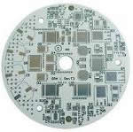
High frequency power amplifier Rogers PCB aplication
-
High frequency power amplifier Rogers PCB aplication
Designing a high frequency power amplifier takes more than just finding the right power transistor. It involves the design of input and output impedance-matching circuits for maximum power transfer and well regulated power-supply circuits. It also requires choosing a printed-circuit-board (PCB) material that will deliver the right combination of performance and reliability for the cost. The right choice of PCB material for an amplifier design can improve gain, gain flatness, gain stability, and output power.
For high frequency amplifiers, the options for PCB substrates are many, from lower-cost FR-4 materials to higher-performance (and higher-cost) PCB substrates materials based on polytetrafluoroethylene (PTFE) dielectric materials. In between these two extremes lie many excellent PCB materials, including some newer thermoset-resin dielectric materials with attractive performance cost ratios. From the low end to the high end, each material selection represents a set of tradeoffs between the quality of physical and electrical characteristics and cost. In choosing one of these materials for an amplifier design, the key is understanding how these different materials characteristics ultimately affect amplifier performance.
The most basic of PCB substrate properties is its permittivity or relative dielectric constant (Dk). For a high frequency amplifier, where signal wavelengths are proportional to the physical lengths of circuit lines and transmission-line structures, the value of the dielectric constant will impact the size of the amplifier’s circuitry, with higher values of Dk resulting in smaller amplifier circuits. For portable designs and products that must be miniaturized, small size can be a positive benefit, although higher-power circuits may need larger circuitry for proper power dissipation. As an example, two members of the RO4000® family of circuit-board laminates from Rogers Corporation, RO4350B™ laminate and RO4360™ laminate, are both hydrocarbon based thermoset-resin dielectric materials but with considerably different Dk values as a result of different filler materials. The RO4350B laminate has a dielectric constant of 3.48 while the RO4360 laminate has a Dk value of 6.15.
For an amplifier, perhaps as important as the Dk value is the consistency of the dielectric constant across the PCB substrate and how the Dk is affected by temperature. In designing an amplifier, one or more power transistors must be impedance matched over a range of desired operating frequencies to the characteristic impedance of the overall circuit or system, usually at 50 Ohms. This impedance transformation requires a circuit-board material that can yield transmission lines with tightly controlled impedances, which requires consistency of the dielectric constant across the length, width, and thickness of the material.
Materials manufacturers provide information on the consistency of their products in terms of a dielectric constant value with an associated tolerance, usually measured in the z-axis (thickness) of the material at some test frequency. For example, the RO4350B laminate has a Dk tolerance of 3.48 ± 0.05 at 10 GHz. The RO4360 laminate has a Dk tolerance of 6.15 ± 0.15 at 2.5 and 10 GHz.
For an amplifier, it is also important that a PCB substrate maintain consistent dielectric constant with temperature. Different substrate materials can be compared in terms of this capability by a parameter known as the thermal coefficient of dielectric constant. It is defined by the amount of change in a material’s dielectric constant in parts per million (ppm) for a given change in temperature in degrees Celsius (°C). Using the RO4350B material again as an example, it has a thermal coefficient of dielectric constant of +50 PPM/°C for ambient temperatures from -50 to +150°C. This means that every 1°C rise in temperature results in an increase of 50 ppm in the value of the material’s dielectric constant.
Another key material parameter to consider when shopping for PCB substrates for an amplifier is dissipation factor or loss tangent. It is a measure of signal energy lost as a result of dissipation through the dielectric material. Ideally, the number for a selected PCB material should be as low as possible to ensure minimal loss in amplifier output power and signal gain. As an example of actual values, the dissipation factor for the RO4350B material is a low 0.0031, with an even lower 0.0030 for the RO4360 material when both are tested at 2.5 GHz.
A comparison was made between various material options using Rogers Corporation’s MWI Impedance Calculator. This simulation tool, besides calculating impedance/line widths for given material parameters, also provides calculations for insertion loss (taking into account copper foil roughness) and a conservative estimate of RF temperature rise based on the frequency of operation. The materials selected were based on unique properties of each and likely candidates for evaluation by designers for these type of applications, Table 1 lists their properties;
1. RT/duroid® 5880 laminate (PTFE/random glass fibers): it has the best electrical properties, low dielectric constant (Dk) and very low loss tangent/dissipation factor (Df), mainly used in aerospace/defense market.
2. RO4350B™ laminate (thermoset resin/woven glass/ceramic filler): it is the most widely used material for power amplifiers used in wireless infrastructure.
3. RO3003™ laminate (PTFE/ceramic filler): best RF performance for commercial grade materials.
4. TC350™ laminate (PTFE/woven glass/ceramic filler): highest thermal conductivity material, commercial grade.
5. RT/duroid 6035HTC (PTFE/ceramic filler): highest thermal conductivity material in the market, aero/def grade.
Calculated temperature rise and insertion loss are shown in Figure 1, for a 50Ω transmission line operating at 250W/2.5GHz on 0.030” dielectric with 1 oz. copper foil. What first stands out is that the material that has the best electrical performance in the group, has the worst thermal behavior and that is driven by the fact that it has the lowest thermal conductivity. Temperature rise of RO4350B material is in line with the best electrical performing, with a thermal conductivity 0f 0.62, this is enough to compensate for the significant increase in Dk and Df. At power levels of 100W or less, as is the case in most wireless infrastructure base stations, RO4350B provides an excellent balance of performance and cost, but going to 250W may require another solution to meet the recommendation of keeping overall temperature rise below 100C.
By reviewing some basic PCB material characteristics and parameters, it can be possible to locate available PCBs that are well suited to LNA and PA circuit designs for a wide range of commercial, industrial, and military applications.
Consistency and stability are two properties that might be considered good starting points for any circuit material being considered as a foundation for either an LNA or a PA (Fig. 1). The power levels and the heat generated by the two types of amplifiers will differ, but maintaining consistent behavior across frequency and temperature for critical PCB material parameters—such as dielectric constant (Dk or εr), temperature coefficient of dielectric constant (TCDk), or dissipation factor (Df)—can benefit the performance of either type of amplifier.
Power-amplifier designers typically create a circuit based on specific active devices for the output stage. While the choice of transistor determines the ultimate performance of an amplifier, printed-circuit-board (PCB) materials can also play a major role in an amplifier design. Selecting optimum substrate materials for an amplifier can improve gain and stability, and enable the maximum output power possible for a design.
High-frequency amplifier designers have a wide array of PCB materials from which to choose, from lower-cost FR-4 and thermoset-resin dielectric materials to higher-performance (and higher costing) dielectric materials based on polytetrafluoroethylene (PTFE) reinforced by woven glass or ceramic filler (Fig. 1). Understanding the electrical and mechanical properties of those materials and how they impact amplifier performance can help guide an amplifier designer through the materials selection process.
High frequency PCBs or RF PCBs are very significant for high reliability products & critical frequency applications like multilayer microwave PCBs, micro strip PCBs & communication applications. We pride in providing our customers RF Boards of excellent quality and high reliability along with all kinds of Rogers-RO /RT series laminates & ISOLA-ITERA laminates most suitable for the RF PCBs.
Our RF Board manufacturing plant is equipped with the latest and most sophisticated machinery and process system aptly suited for the manufacture of such PCBs.
While Rogers RO series RF laminates are predominant in mobile phone antennas, T/R modules, multilayer boards, networking at 1G, 100G,40G, 100G etc., RT series laminates RT5000, RT6000, TMM etc. are designed for space & defense applications.
All substrate materials are defined by their permittivity (e). The parameter describes the capability of a material to act as an insulator of electrical charges as well as by its capability to store charges. Substrate materials are typically defined by measuring their permittivity relative to that of a vacuum, which is unity or 1. Because it is referenced to a vacuum, the relative permittivity (or dielectric constant), ei, of a substrate material is always greater than 1. For most high-frequency circuits, vendors offer substrate materials with dielectric constants from about 2 to 10 as measured in the z-axis of the material (or through the thickness of the material).
The basic trade off in substrate materials with lower versus higher values of dielectric constant is the levels of insulation provided by the materials. Materials with lower relative dielectric constants provide excellent isolation for lower-frequency signals, particularly in dense circuits with closely spaced conductive lines. Materials with higher relative dielectric constants provide a means by which a circuit can be reduced in size and are usually used in lower frequency applications or where the size of a board needs to be minimized.
LNAs are typically compared for a given bandwidth by a number of key performance parameters, including noise figure, small-signal gain, and output power at 1-dB compression. Ideally, noise figure remains consistently low even with increasing frequency and temperature. LNA noise figure is highly dependent on tight impedance control of the LNA circuitry (often at 50 Ω), and tight impedance depends on a number of different circuit material characteristics. These include variations in PCB material thickness, variations in Dk across the material, and changes in Dk as a function of temperature.
So far, the factors in considering a PCB material for an amplifier design have focused on the importance of being able to fabricate circuits with consistent impedance. Ensuring that a PCB material’s dielectric constant remains stable across the material’s dimensions and with temperature can help, but what about the effects of high-humidity environments? Many amplifiers designed for cellular networks are mounted in towers or outdoors where they can be exposed to conditions of changing humidity. PCB materials suppliers evaluate their products in terms of a parameter known as moisture absorption. When moisture is absorbed by a substrate, it is essentially adding water, with a dielectric constant of about 73, to a material with a much lower dielectric constant. Depending upon the percentage of moisture absorption, the shift in dielectric constant can be significant. Some PCB laminates, for example, suffer moisture absorption as high as 2 percent which will effectively raise the dielectric constant, resulting in a change in impedance, increase in reflected signals, and reduction in amplifier gain. Substrates engineered to minimize changes in dielectric constant under high-humidity environments are usually characterized by low values of moisture absorption. For example, RO4360 laminate has moisture absorption of only 0.13 percent, even when submerged in warm water for 48 hours.
RT/duroid 6006 microwave laminates feature ease of fabrication and stability in use. They have tight dielectric constant and thickness control, low moisture absorption, and good thermal mechanical stability.
RT/duroid 6006 laminates are supplied clad both sides with ¼ oz. to 2 oz./ft2 (8.5 to 70 μm) electrodeposited copper foil. Cladding with rolled copper foil is also available. Thick aluminum, brass, or copper plate on one side may be specified.
Rogers RO3000 series
Features and Benefits: Low dielectric loss (RO3003 laminates) Laminates can be used in applications up to 77 GHz. Excellent mechanical properties versus temperature Reliable stripline and multi-layer board constructions. Uniform mechanical properties for a range of dielectric constants Ideal for multi-layer board designs with a…
Go to post »
Nelco N9000
Nelco N9000
Application: Cellular Base Station Antennas Wireless Communications Power Amplifiers Dual Band Hi Power Passive Circuits Automotive Applications Digital/Microwave Hybrid Multilayer PCB Assemblies Millimeter Wave Components Telecommunications
Go to post »
Nelco N9000-13 RF
Nelco N9000-13 RF
N9000-13 RF is a next generation PTFE Performance Blended product which combines the RF electrical properties of PTFE with the competitive performance features of Nelco’s proprietary N4000-14 epoxy. Features: Blended material offers the mechanical performance of a thermoset epoxy with the electrical performance of PTFE…
Go to post »
« Older Entries
Abstract- In this paper we present design and implementation of a high efficiency Class E, Radio Frequency (RF), Power Amplifier (PA) with Gallium-Nitride (GaN), High Electron Mobility Transistor (HEMT). The proposed RF PA shows 17 W output power. We have used binomial matching network circuit for achieving required Band Width (BW). The proposed RF PA works with 28V power supply voltage and has more than 63% efficiency in working BW. In tradeoff between power efficiency and linearity and for achieving the required linearity of /4-DQPSK modulation, we try to implement our structure near to EB-class instead of E-class. We can obtain two ton Intermodulation Distortion Third Harmonic (IMD3) in this condition better than -26 dBc in-band. Also we measure AM to AM conversion better than 0.3 dB/dB and AM to PM conversion less than 3.5 Deg/dB. We implemented our design with a Rogers printed circuit board (PCB) on a Cu hot plate for better thermal transferring. Keywords: RF, PA, GaN, HEMT, Class E, Binomial. I. INTRODUCTION The Radio Frequency (RF) Power Amplifier (PA) is basically an electronic circuit which transfers the RF power to the load by amplifying the input power. The power amplifier design involves many challenging concerns at the same time such as output power, efficiency and linearity. Also the technology and type of transistor is important in the design of RF PAs. Figure 1 shows typical RF frontend of a transmitter. The RF signal has been amplified by PA just before the antenna. As exhibited in Figure 1, the final block before the antenna is a High Power Amplifier (HPA). In this block the power of signal reaches the maximum value. Because of high power consumption, the efficiency of this stage is the most important block in determining the efficiency of the transmitter [13]. Most of the time a Gallium-Nitride (GaN), High Electron Mobility Transistor (HEMT) was chosen for the RF PAs. The parasitic capacitances of GaN HEMTs ar
Double-sided pcb have one layer dielectric layer in the middle, both sides are traces layer. Multilayer PCB is a multilayer traces layer, a dielectric layer between each 2 layer, a dielectric layer may be made very thin layers . Multilayer circuit board having at least three conductive layers, wherein the outer surface 2layers, while the remaining one was synthesized in the insulating plate. Electrical connection between them is usually done by plated through holes in the circuit board on the implementation of the cross section
Choosing the right circuit-board material can be a frustrating experience. After all, every manufacturer of printed-circuit-board (PCB) materials promises outstanding performance for their products, offering an array of dielectric formulations to achieve improved stability, or power-handling capability, or lower loss. Wouldnât it be simpler to choose one material, such as FR-4, for all applications? In an ideal world, a single PCB material could serve all applications. But requirements for two applications may vary so widely, that no single PCB material can provide optimum performance for both.
For example, temperature coefficient of dielectric constant (TCDk) describes how a material’s Dk changes with temperature; TCDk is analogous to Df in that it can provide tremendous insight into a PA’s expected performance over a given temperature range. The coefficient of thermal expansion (CTE) is another circuit material parameter that is key to providing insight into an amplifier’s performance with temperature. CTE is related to the reliability of a circuit-assembly process (and the different temperatures used in manufacturing a PCB) and the long-term reliability of a PA or other circuit, especially those that must operate over wide temperature ranges. Thermal conductivity is yet another important PCB parameter for PA designers, since it is critical to the thermal management of a PCB and can provide insight into how much heat and power a PA will be capable of handling.
Understanding a PCB’s TCDk can be especially important for PAs, where the power delivered by the amplifier is never 100 percent efficient and will raise the temperature of the circuit. These thermal effects are added to the environmental operating temperatures, and a circuit material’s Dk will change according to its TCDk parameter. In particular, amplifiers that have been developed in laboratory environments under controlled conditions and then faced with in-field operating conditions may experience considerable different thermal conditions in the field, with greater impact on Dk. For a PA, where consistent Dk is vital to maintaining the tightly controlled impedance of the matching circuits that help achieve maximum gain and output power, excessive changes in Dk will result in larger-than-expected changes in impedance in these matching circuits, resulting in gain and output-power variations over temperature for a PA.
As a general rule, the TCDk of a PCB material should be better (lower) than 50 ppm°C, with this as an absolute value. Circuit materials based on polytetrafluroroethylene (PTFE) exhibit poor TCDk values, typically around 150 ppm/°C, which indicates much greater variations in Dk with temperature. As a result, most PTFE-based laminates used for high-frequency applications feature glass reinforcement or are filled with materials that can help maintain the stability of the Dk with temperature. Often, ceramic materials are used as filters; they can alter several properties of the PTFE laminate and greatly improve the TCDk of the circuit material.
Previous blogs examined some of the key material parameters pertaining to high-frequency laminates, such as dielectric constant, thermal conductivity, coefficient of thermal expansion (CTE), and even flexibility when used in conformal circuits. But how does an engineer combine all this information about a materialâs electrical and mechanical properties when trying to choose the perfect substrate for a particular application? It can be a complex process, but it may be possible to simplify that process.
RF power amplifier (RF PA) is an important part of a variety of wireless transmitters. In the former circuit of the transmitter, the modulation signal generated by the oscillation circuit power is very small, need to go through a series of amplifying a buffer stage, the middle amplifier stage, the final power amplifier stage, get enough RF power to feed To the antenna radiation out. In order to obtain a sufficiently large RF output power, an RF power amplifier must be used.
RF power amplifier pcb play an important part in the RF power amplifier.
We have more than 7 years in high frequency pcb field, power amplifier printed circuit boards are our main products
If you have any relative pcb case,can feel free to send requirements to our factory,we have professional engineer to deal with it
RF power amplifier operating frequency is high, but the relative frequency band is narrow, RF power amplifiers are generally used as the load-frequency network load circuit. RF power amplifier can be divided according to the current conduction angle, A , B , C three working conditions. Class A amplifier current conduction angle of 360 °, suitable for small-signal low-power amplifier, Class B amplifier current conduction angle is equal to 180 °, Class C current conduction angle is less than 180 °. Class B and Class C are suitable for high-power working conditions, Class C working state of the output power and efficiency is the highest of the three working conditions. RF power amplifier mostly works in Class C, but the current waveform distortion of Class C amplifier is too large, can only be used for the use of tuned loop as the load resonance power amplification. As the tuning circuit with filtering capability, loop current and voltage is still close to the sine wave, the distortion is small.
In terms of controlling the heat generated by a power amplifier, a PCB material’s coefficient of thermal expansion (CTE) and its thermal conductivity can serve as useful parameters when considering different materials for an amplifier design. Materials suppliers measure the CTE in all three of a laminate’s axes (x, y, and z). Ideally, all three values should be as low as possible, denoting minimal physical change in a material with changes in temperature. In the x and y directions, the CTE is usually designed to match that of the copper laminated on the dielectric material (about 17 ppm/°C). For multilayer circuits, in which plated through holes (PTHs) are used to make electrical connections between layers, the CTE in the z-axis (thickness) is critical to ensure good PTH reliability. In general, a material with z-axis CTE of 70 ppm/°C or less will provide good PTH reliability. As an example, Rogers RO4350B laminate has CTEs of 14 and 16 ppm/°C, respectively, in the x and y axes and 35 ppm/°C in the z axis. RO4360 laminate has CTEs of 16.6 and 14.6 ppm/°C, respectively, in the x and y axes and 30 ppm/°C in the z axis.
The Advanced Circuit Materials (ACM) Division of Rogers Corporation has introduced RO4360 laminates, developed for the special requirements of high-frequency amplifier designers. RO4360 laminates feature a dielectric constant of 6.15 and loss of 0.003 @ 2.5GHz. The laminates are based on a ceramic-filled, thermoset resin system reinforced by glass fiber for excellent mechanical stability compared to PTFE woven glass.
RFMW PCBs are used in applications where transmission rates are critical. The types of PCBs often incorporate the use of controlled impedance designs as well as PTFE, Ceramic, or other high-speed materials. Common design features include hybrid material constructions, blind & buried vias, backdrilling, and sequential laminations.
Manufacturing challenges typically surround the different types of materials required by the design. Primarily the issues include drilling, multilayer lamination, and plating activation. Our engineering team devised numerous process controls and machine recipes to address these issues such that we are able to produce the most complex designs in short amounts of time.
These improved oxidation resistance circuit materials exhibit x- and y-axis expansion coefficients similar to that of copper. RO4835 laminates are RoHS-compliant, do not require special preparation, and can be processed using standard fabrication methods. Typical applications include automotive radar and sensors, point-to-point microwave backhaul units, power amplifiers and phased-array radar.
RO4360G2 laminates have a tailored high Dk of 6.15 @ 10 GHz, which allows next generation power amplifier designers to meet size and cost reduction targets. Specifically, the laminates’ higher Dk allows for a significant reduction in finished circuit board size (20-30%). RO4360G2 laminates process similar to FR-4, are automated assembly compatible, and offer the same reliability and repeatability that customers have come to expect from Rogers RO4350B material.
With a UL 94V-0 flame rating and fully lead-free process capable, these laminates possess excellent thermal conductivity of .81 W/m/K for improved reliability, a low Z-axis CTE for reliable plated through holes, and drill performance as good as or better than RO4350B laminates.
COOLSPAN TECA film is a thermally and electrically conductive adhesive that is designed for bonding circuit boards to heavy metal backplanes, heat sinks, and housings. The thermosetting, epoxy-based, silver-filled adhesive is a practical alternative to fusion bonding, sweat soldering, press-fit, and other mechanical approaches for attaching circuits to associated structures. COOLSPAN TECA film, which is supplied in sheet form on a PET carrier, is able to survive lead-free-solder processing and offers outstanding chemical resistance and high temperature performance, helping designers to keep things cool.
For PCB West 2014 Conference attendees, Rogers’ John Coonrod will be examining why some PCB materials are better than others at achieving low insertion loss, during his presentation “Variables of PCB Fabrication and Design that Affect Insertion Loss.” September 10 at 11 AM. Coonrod, who holds a bachelor’s degree in Electrical Engineering from Arizona State University, is a Sr. Market Development Engineer for Rogers Advanced Circuit Materials Division. He has over 25 years of experience in the PCB industry, working with flexible, rigid, and high-frequency PCB materials.
RO4360 laminates provide the performance and reliability designers need in a lower total PCB cost solution. Building on the successful legacy of the company's RO4350B laminate materials, the new product features low dissipation factor, generous power-handling capability, and improved thermal conductivity. Environmentally friendly RO4360 laminate materials are RoHS compliant and compatible with standard printed circuit board processing methods. The copper-clad laminates exhibit a high glass transition temperature (Tg) of greater than 280ºC and a low coefficient of thermal expansion (CTE) in the z-axis (30 PPM/ºC) needed for reliable plated through holes (PTHs) in multilayer circuits.
When considering circuit materials for millimeter-wave applications, another important material parameter is TCDk. This is a measure of how much a material’s Dk will change as a function of temperature and ignoring other factors, such as moisture absorption. Ideally, a circuit material would have a TCDk of 0 ppm/°C, or no change in Dk as temperature changes. Realistically, the lowest possible values of TCDk are desirable to minimize variations in Dk with temperature. As an example, RO3003 laminate has a TCDk value of -3 ppm/°C, which is extremely low and less than 50 ppm/°C as an absolute value. It denotes minimal change in Dk with temperature, for stable electrical performance even when operating within the temperature extremes of automotive sensors. Figure 3 plots changes in Dk with temperature, relative to room temperature or +25°C and normalized to a value of 1.00, for a number of different circuit materials used for high-frequency applications, including RO3003 laminates and low-cost FR-4 materials often used in hybrid PCB circuits. As the curve for RO3003 laminate shows, this material remains extremely close to the nominal value of 1.00 from -50 to +150°C, which is due to the low TCDk value for this material.
Because wavelengths are so small at millimeter-wave frequencies (decreasing in size with increasing frequency), the composition of circuit materials should be considered when choosing a circuit material for applications at millimeter-wave frequencies. Extremely small circuit features are needed in support of higher frequencies. For example, at 79 GHz and using a 5-mil-thick circuit material with Dk of about 3, a 50-Ω microstrip transmission line will have a wavelength of about 0.095 in. (2.413 mm). Circuit dimensions equal to a quarter wavelength at 79 GHz—0.024 in. (0.603 mm)—can cause unwanted resonances. Circuit materials employ different materials, such as woven glass, as reinforcement for added strength. Some circuit materials may employ glass cloth with physical features within the dimensional range of quarter wavelengths at millimeter-wave frequencies. These materials can suffer from this “glass weave effect” at millimeter-wave frequencies, with areas on the material that exhibit variations in Dk resulting in impedance and phase variations at millimeter-wave frequencies. This effect typically surfaces as circuit-to-circuit variations.
RO4360 laminates allow designers to reduce circuit dimensions in applications where size and cost are critical. They are the best value choice for engineers working on designs including power amplifiers, patch antennas, and other commercial high-frequency applications.
Eurocircuits are specialist manufacturers of prototype and small batch PCBs. We are experts in order-pooling. Placing different orders on a standard production pooling panel minimizes set-up and production costs so you get good prices and no tooling charges. Because of the large numbers of orders we receive daily, we can offer a large number of technological options in our pooling services. We do a 100% check on your data before manufacture to make sure that you get the boards you want.
Yang Xi Rogers Advanced Circuit Materials Division Asia Pacific market development manager , said the application of high-frequency plate is very broad and can cover most of the market applications: base station amplifier design requirements used in high-power, low insertion loss of material ; antenna applications require a certain hardness of the plate , and there are very good indicators of passive intermodulation ; automotive applications require sheet with long-term reliability , and can withstand high temperatures ; application types on mobile phones and high-speed circuit is also very rich.
Amplifier design very seriously and insertion loss performance of heat dissipation plate . Rogers has a RO3 0 3 5 HTC plates, which insertion loss is 0. 0017 , the thermal conductivity of 1.44 , ideal for power amplifier applications. Small insertion loss means less heat generated , plus good thermal conductivity, the heat can be dissipated quickly , so that the surface temperature of the circuit board and the amplifier tube temperature.
In antenna applications , the insertion loss is important , but more important is the passive intermodulation . Rogers antenna grade laminates RO4725JXR and RO4730JXR it has good intermodulation index . Meanwhile , in some scenarios the antenna , it is also required to have certain hardness or multilayer_ design. RO470 0JXR series plate hydrocarbon -based resin system with sufficient hardness and can be the same as FR-4 sheet multi- processing and mixed pressure , ideally suited for such applications .
Rogers Corporation will be showing samples of the company’s wide range of industry-leading PCB materials at the Del Mar Electronics & Design Show (DMEDS), April 30-May 1, 2014, at the Del Mar Fairgrounds in San Diego, California.
Representatives from Rogers Corporation will be at booth #622 with information and insight on the use of their circuit materials, including COOLSPAN TECA film, RO4835 high-frequency laminates, and RO4360G2 high-frequency laminates.
Rogers COOLSPAN TECA film is a thermally- and electrically-conductive adhesive that is ideal for bonding circuit boards to heavy metal backplanes, heat sinks, and housings. The thermosetting, epoxy-based, silver-filled adhesive is a practical alternative to fusion bonding, sweat soldering, press-fit, and other mechanical approaches for attaching circuits to associated structures. COOLSPAN TECA film, which is supplied in sheet form on a PET carrier, is able to survive lead-free solder processing and offers outstanding chemical resistance and high-temperature performance, helping you to keep things cool.
Help from the Eurocircuits community!
ChipDesign a Belgian Eurocircuits customer is specialized in IC design and turn-key RF solutions: Antennas and antenna arrays, FPGA design, Packaged MMICs, PCB design, PDK development, Power amplifiers and SSPA transmitters. In the field of RF, ChipDesign has developed a general-purpose RF/microwave library for CadSoft Eagle, which it offers free-of-charge. It can be downloaded here.
Storm Circuit is one of the most important PCB manufacturers for your RF/Microwave/high frequency circuits in China.we not only make the PCBs,we can help to cut cost if you can not find the material . Yes,
some material is a bit difficult to source ,they are made in USA and with top cost. The most important is you have to verify your design first ,so it is prototype. Some material has MOQ,like 5 big sheets for Rogers 3003 or 6002,and takes so long , 2 months ,even longer . Can you wait? or can your project wait?
Normal Rogers material RO4003,4350,5880,6002.Taconic material TLX ,and other PTFE(Teflon)material.
RF/Microwave/HF applications:
Communications
Traditional telecommunication equipment, FTTP, VOIP, multimedia services, data networking and IT infrastructure products, wireless infrastructure products, power amplifiers, splitters and combiners, high power transistors, etc.
Some of the projects listed on this site produced requests for PC boards and other parts, so here they are.
Instructions on assembling and use are contained in the articles on this site, as well as close-up component layout pictures to aid in assembly. Surface-mount parts are used throughout, so it is helpful to have some experience in working with them. There is a video here showing some of the techniques used in working with these components.
As with all electronic oscillation, motorboating occurs when some of the output energy from an amplifying device like a transistor or vacuum tube gets coupled back into the input circuit of the device (or possibly into an earlier stage of the amplifier circuit) with the proper phase for positive feedback. This indicates there is an unwanted feedback path through the circuit from output to input of an amplifying stage. The technical conditions for oscillation, given by the Barkhausen stability criterion, are that the total gain around the feedback loop (comprising the amplifying device and the feedback path) at the oscillation frequency must be one (0 dB), and that the phase shift must be a multiple of 360° (2π radians). Since most amplifying devices, transistors and tubes, are inverting, with the output signal 180° opposite in phase from the input, the feedback path must contribute the other 180° of shift.
Many types of parasitic oscillation are caused by small interelectrode capacitances (parasitic capacitance) or mutual inductance between adjacent wires or electronic components on the circuit board, which create an inadvertent feedback path. However these usually cause oscillations of high frequency, at the upper end of or above the passband of the equipment. This is because the phase shift of the small reactances in the feedback path, which increases with frequency, only become significant at high frequencies. Low frequency oscillations like motorboating indicate that some device or circuit with a large time constant is involved, such as the interstage coupling capacitors[6] or transformers, or the filter capacitors and supply transformer winding.[6]
One common cause is feedback through the plate power supply circuit.[2][6][4] The power supply provides DC current to each tube's plate circuit, so the power supply wiring (power busses) can be an inadvertent feedback path between stages. The increasing impedance of the filter capacitors at low frequencies can mean that low frequency swings in the current drawn by output stages can cause voltage swings in the power supply voltage which feed back to earlier stages,[2][6][4] making the system a subaudio oscillator. This is caused by inadequate power supply filtering or decoupling. The electrolytic capacitors used in equipment of 1960s vintage contained liquid electrolyte, which dried out over decades, decreasing the capacitance and increasing the leakage current, and these are often the cause.
One solution suggested is a "capacitor job", replacing all the old electrolytic capacitors.[4][11] A more radical but comprehensive solution is to add modern IC voltage regulators, or replace the entire power supply with a modern regulated one.[4]
You can order any of the items listed here using the shopping cart provided, or by sending an email (see contact information above). Payment can be made with your Paypal account (if you have one), or a credit card of your choice at checkout. Parts are usually sent Priority Mail the next business day. Postage is added at checkout, and can be as low as $7.50 within the U.S., and $15 U.S.D. International (first class mail). Usually, several kits or parts can be sent in the same box for no additional postage. It can get a bit complex, but the checkout shipping calculator will figure it out for you.
Computer Peripherals
High end printers, cable modem, wireless routers, IP telephones, consumer and office products, banking system etc.
Rogers PCB Introduction:
Rogers High Speed PCB widely used in the area of high speed technologies like communication device,RF wireless boards, High speed Electronics,Aerospace satellite, Military industry and so on. PCBSINO have years experiences in the Rogers Production line of high frequency microwave business, for which widely apply to power divider,combiner,power amplifier,line amplifier,base station,RF antena,4G antena etc. our Rogers material stock as below:
RO4000 material is very similar to that of copper which allows the material to get excellent dimensional stability, a property needed for mixed dielectric multilayer boards constructions.
now PCBSINO RO4003™ laminates are currently offered in various congurations utilizing both 1080 and 1674 glass fabric styles, with all congurations meeting the same laminate electrical performance specication.
PCBSINO can make Rogers pcb base on your detail requirements.
Specically designed as a drop-in replacement for the RO4350™ material, PCBSINO RO4350B™ laminates utilize RoHS compliantame-retardant technology for applications requiring UL 94V-0 certication. These materials conform to the requirements of IPC-4103, slash sheet /10 for RO4003C and /11 for RO4350B materials.
RO4000 Series is High Frequency Circuit Materials.
Consumer
Computers, televisions, cameras, digital video recorders (DVR), handheld products, LED, etc.
Automotive
Passenger safety systems, engine control systems, air bags, traction control products, etc.
High End Computing and Storage
High performance computer and server, mainframe system and storage equipment, memory, etc.
Industry
Power supply, main control panel, monitor, CCTV products,automotive control equipment, industry robot, access control products etc
Medical
Magnetic resonance imaging (MRI), computed tomography (CT), emergency response defibrillation units, patient monitoring, implantable devices, robotic surgery systems, biometrics and diagnostic equipment, etc.
Radar system
Global positioning system antenna
Phased array antenna
Spotlight network
Space satellite transceivers
power amplifiers and antennas
Millimeter Wave Applications
For furhter information, please feel free to contact us, www.pcbsino.com