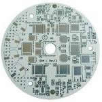
Electronic regulator for automobile Aluminum mcpcb aplication
China PCB Manufacturing, Shenzhen PCB Manufacturer, Making Circuit boards
PCB Contract manufacturer, PCB Fabrication, Turnkey assembly services
Buy Print circuit board, customer: /USA/UK/Canada/South Africa...
PCB Supplier Shenzhen, China, PCB Manufacturer, Turnkey services
-
PCBSINO is the Top 5 PCB manufacturer company in China.
PCBSINO do rapid Prototype within 24 hours. our rigid PCB like MCPCB and Rogers PCB, FR4, High TG FR4, Rogers 4003, 4350,Al Aluminum metal Core MCPCB, Al2O3 Ceramic,Taconic,Halogen Free material, CEM-3, Fr2, CEM-1, CEM-2, 94VO, Rogers HF material, Polymide, etc.
PCBSINO making many type electronic product for our customer, Our turkey services team can source original components part for your project(Digikey/Mouser/RS...), senior Electronic engineer will follow each step of the production to solve any PCB problem and our team will do final function test in PCB house.
Express PCB |
|
Rigid PCB Rapid Prototype,24 hours |
| Fr4 PCB |
|
prototype Lower to 15USD ! |
| Rapid Prototype |
|
Fr4 Rigid PCB Rapid Prototype China, |
MCPCB |
|
MCPCB Manufacturer China, Shenzhen |
| Aluminum PCB: |
|
Aluminum Metal Core PCB manufacturing, Fabrication |
| Aluminum PCB: |
|
single side, double side MCPCB, 0.5-5mm or more |
Rogers 4350B |
|
Rogers 4350,Rogers 4003 Manufacturing |
| Rogers 4350B |
|
Rogers 4350B,4003C PCB Manufacturer |
| Ro4350B |
|
Rogers High Frequency PCB Manufaturing China |
Turnkey Services |
|
Turnkey PCB Assembly Services, |
| Turnkey services |
|
Print circuit board Manufacturing, Turnkey Services |
| Turnkey Assembly |
|
Through Hole PCB components wave soldering Assembly |
Electronic regulator for automobile Aluminum mcpcb aplication
-
Electronic regulator for automobile Aluminum mcpcb aplication
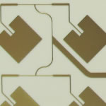
The MCPCB commonly consists of a metal core layer (typically aluminum or copper), a continuous dielectric layer and a copper circuit layer. Protecting electronic components by removing heat, metal base boards feature a thermally conductive dielectric layer connecting IC’s to the heatsink.
Sample Metal Boards
Industries
LED Lighting (general, automotive, and backlighting) to include high-current and spotlight, Electric Vehicles, Alternative Energy to include Solar applications, High Density Power Conversion, Motor Control, DC-DC Converters and Flat Panel Displays. Automotive applications include power regulators and controllers, exchange converters, optical systems. Industrial Power applications includes high-power transistors, arrays, solid-state relays.
LED PCB Solutions
Sample Metal Boards
Click the image below for LED sample boards and board specifications.
Aluminum plate is a unique metal-based CCL, with good thermal conductivity, electrical insulation properties and machining performance. Widely used in LED, air conditioning, cars, ovens, electronic, lights, high power and so on.
Metal core PCB is a unique layered system comprised of base layer, circuit layer and dielectric layer.Base Layer is usually aluminum, could also be copper or iron alloy, Thickness is from 0.5mm to 4.0mm, standard is 1.5mm. Circuit layer is copper foil with thickness of 1oz to 6 oz. Dielectric layer is a layer of thermal insulation materials with low thermal resistancem
Metal Core PCB Sample Introduction
Flexible Electronic Printed Circuit Board Prototyping Service , Iron PCB Board MCPCB
Large Image : Flexible Electronic Printed Circuit Board Prototyping Service , Iron PCB Board MCPCB
Product Details:
Place of Origin: Shenzhen, China
Brand Name: AGILECIRCUIT
Certification: ISO9001,UL, RoHs, TS16949
Model Number: coppercladpcb6060
Payment & Shipping Terms:
Price: Quote by Gerber
Packaging Details: Vacuum and Outter Carton
Delivery Time: 1 week - 2 weeks
Payment Terms: TT, West Union,Paypal,MoneyGram, NET
Trade Terms:: EX-WORK, DDU TO DOOR, FOC
Detailed Product Description
Flexible Electronic Printed Circuit Board Prototyping Service , Iron PCB Board MCPCB
Product Name:
Copper Clad PCB
Material:
Copper metal core
Layer Count
Single Layer
Board Thickness:
1.5mm
Copper 1oz Surface Finishing
OSP
Aplication
DC / AC converter
Original
China PCB Manufacturer
Descriptions:
Copper clad PCB is a kind of metal core PCB whose cost is much higher than aluminium. The heat dissipation is many times better than the aluminum clad PCB and iron PCB board, usually used in electronic equipment with high heat dissipation requirement, such as industrial power equipment, car, motorcycle ignition, regulator, speakers, power supply modules
Separated with finishing, there are immersion gold copper clad PCB, immersion silver copper clad PCB, HASL copper clad PCB , OSP copper clad PCB ect.
Copper clad PCB requires a large current-carrying capacity, which need to realized with thick copper foil. Copper thickness is usually from 35μm ~ 280μm. The thermal insulation layer is the core technology of copper clad PCB.
If its the first time you've visited our site, then why not Register your details with us and we'll keep you informed on What's New and Special Offers.
Welcome to Rabtron, one of South Africa's leading Electronic Components Retailer
How to order....
Customers will need to Register to create an Account
The registration process takes only a few minutes and will enable users of this web site to then place orders, or update their account details.
Registered customers can place their on-line orders using this website. We offer various methods of dispatch, depending on your order weight/volume and your destination. On completion of your order the options applicable will be displayed.
Alternatively, you can Visit us and purchase goods direct from our Store in Vereeniging.
We accept Visa Card, MasterCard and bank deposits
Need more information? Please feel free to contact us
Product Categories
semiconductors
passive components
connectors
ac dc adaptors
batteries
Heat flow is just like current flow, only there is no 'return', heat always always always flows from higher potential to lower potential. Potential being heat energy, in this case. Power is our current. And, conveniently, thermal resistance is...resistance.
Otherwise, it is exactly the same. Watts are your amps, your current. And indeed, this makes sense, as more watts means more heat flow, right? And just like voltage, the temperature here is relative. We are not talking about absolute temperature at any point, but only the temperature difference, or potential difference, between to things. So when we say that there is, say, a 10°C temperature potential, that simply means one thing is 10°C hotter than the other thing we're talking about. Ambient temperature is our 'ground'. So to translate all this into real absolute temperatures, you simply add it on top of whatever the ambient temperature is.
Things like your LM7805 that produce heat are perfectly modeled as constant current sources. Because power is current, and it is acting like a constant power device, constantly generating 4.4W of heat, so it's like a constant current source generating 4.4A. Just like constant current sources, a constant power source will increase temperature (like the voltage of a constant current source) as high as it needs to maintain the current/power. And what determines the current that will flow? Thermal resistance!
1 ohm is really saying that you will need 1 volt of potential difference to push 1A through it. Likewise, while the units are funky (°C/W), thermal resistance is saying the same. 1 °C/W is just like one Ω. You will need 1°C of temperature difference to push 1 watt of thermal 'current' through that resistance.
Better still, things like voltage drops, parallel or series thermal circuits, it is all the same. If a thermal resistance is just one part of a larger total thermal resistance along your thermal path ('circuit'), then you can find the 'voltage drop' (temperature increase) across any thermal resistance in exactly the same way you would find the voltage drop across a resistor. You can add them for series, 1/(1/R1....1/Rn) just like you would for parallel resistances. It all works and without exception.
2. But it takes time for things to get hot!
Ohm's law is not really a law, but was originally an emperical model, and later realized was just the DC limit of Kirchoff's law. In other words, ohm's law only works for steady state circuits. This is likewise true for thermals. All that I wrote above is only valid once a system has reached equilibrium. That means you've let everything that is dissipating power (our constant 'current' power sources) do that for a while and so everything has reached a fixed temperature, and only by increasing or decreasing the power will anything's relative temperatures change.
This usually doesn't take too long, but it also isn't instantaneous. We can see this quite clearly simply because things take time to heat up. This can be modeled as thermal capacitance. Basically, they will take time to 'charge', and you'll see a large temperature difference between a hot object and a cool one, until they reach equilibrium. You can think of most objects as at least two series resistors (for one point of thermal contact and the other. The top and bottom of your pad, for example) with a capacitor in between. This is not particularly relevant or useful in this situation, where all we care about is steady state, but I thought I'd mention it for completeness.
3. Practicalities
If we are equating heat to electrical current flow, where is it all flowing too? It is flowing into the environment. For all intents and purposes, we can usually think of the environment as a giant, infinite heatsink that will maintain a fixed temperature no matter how many watts we push into it. Of course, this isn't quite the case, rooms can get hot, a computer can certainly heat up a room. But in the case of 5W, it is fine.
The thermal resistance of the junction to case, then case to pad, pad to the pad on the other side of the pcb, bottom pad to heatsink, and finally, heatsink to air, form our total thermal circuit and all of those thermal resistances added up is our true thermal resistance. Those graphs you're looking at, those are looking at the resistances of just one piece of the system, NOT the total system. From those graphs, you'd think a square of copper could dissipate a watt and only rise 50°C. This is only true if the circuit board is magical and infinitely large and will never warm up. The junction in question will be 50° hotter than the circuit board, but that's not very useful if you've heated the circuit board to 200°C. You've exceeded the operating temperature either way.
The unfortunate reality is that natural convection is pretty terrible at cooling stuff. Heatsinks have lots of surface area to increase convection cooling, and are often anodized black to increase their radiative cooling (black objects radiate the most heat, while shiny/reflective objects radiate almost none. Just like an antenna, being good at transmitting makes it good at receiving, and that is why darker to black things get so hot in the sun, and shiny things hardly get hot at all. It works both ways). But you'll find that most heatsinks have a pretty high thermal resistance for natural convection. Check the datasheet, often the thermal resistances of heatsinks are ones for a certain minimum CFPM of air flow over the heatsink. In other words, when there is a fan blowing air. Natural convection will be much poorer in thermal performance.
Keeping the thermal resistances between the junction and heatsink is relatively easy. Solder joins have negligible thermal resistance (though solder itself is not a very good conductor of heat, at least compared to copper), and copper is second only to silver (among normal, non-exotic materials at least. Diamond, graphene etc. are more thermally conductive but also not available on Digikey). Even the fiberclass substrate of a circuit board isn't totally terrible at conducting heat. It's not good, but its not terrible either.
The hard part is actually dissipating the heat out into the environment. That is always the choke point. And why engineering is hard. Personally, I design high power DC/DC converters (amongst other things). Efficiency stops being something you want, and becomes something you NEED. You NEED % efficiency to make a DC/DC converter as small as it needs to be, because it simply will not be able to shed any additional waste heat. At this point, the thermal resistances of individual components are meaningless, and they are all tightly coupled on a slab of copper anyway. The entire module will heat up until it reaches equilibrium. No individual component will actually have enough thermal resistance to overheat theoretically, but the entire board as a bulk object can heat up until it desolders itself if it can't shed the watts quickly enough into the environment.
And, as I said earlier, natural convection is really really terrible at cooling things. It's also primarily a function of surface area. So a plate of copper and a circuit board with the same circuit area will have very similar thermal resistances to the environment. The copper will make the heat more uniform throughout it, but it won't be able to shed any more watts than fiberglass.
It comes down to surface area. And the numbers are not good. 1 cm^c represents about 1000°C/W of thermal resistance. So a relatively large circuit board that is 100mm x 50 mm will be 50 squares, each a square centimeter, and each a parallel thermal resistance of 1000°C/W. So this board has a resistance to ambient of 20°C/W. So, in your case of 4.4W, it won't matter what you do on the board, pad size, thermal vias, any of that. 4.4W is going to heat up that board to about 88°C above ambient. And there is no getting around it.
What heatsinks do is fold a lot of surface area into a small volume, and so using one will lower the overall thermal resistance and everything gets less hot. But all of it will warm up. Good thermal design is as much about directing where heat flows as it is removing it from your widget.
You've done a pretty good job with your heatsink and enclosure setup. But, you are concerned about the wrong things. There isn't a simple way to calculate the thermal resistance of the pad through the pcb, but it only takes around 17% of a pad's area dedicated to vias before you hit diminishing returns hard. Usually using 0.3mm vias with 1mm spacing and filling the thermal pad like that will give you as good as you will get. Just do that, and you'll have no reason to ever worry about the actual value. You care about the system as a whole, not one junction.
What does a capacitor do?
Capacitors are energy-storing devices. A capacitor hinders the flow of electricity between two ends so that it can store that energy. This saved energy can be used later as needed. For example, once a capacitor gets charged, it can replace a battery in a circuit for a short period of time. Therefore, we can say that a capacitor acts like a battery. Most capacitors quickly run out of stored energy but unlike batteries, they be charged again very quickly and reused.
How many are there?
Annual capacitor sales are about $1,200 million. That’s about $3.50 per American.
What is the capacitor made of?
Capacitor is a sandwich that consists of: two electricity- conducting plates with an insulator in between. The insulator can be anything that does not conduct electricity, but most commonly used are paper, glass, rubber, ceramic, and plastic. The conducting plates can be any metal that lets electricity flow easily — for example, aluminum, tantalum, and silver. In general, the smaller the distance between the metal plates, better the larger the capacitor and the more energy it can store.
Are capacitors dangerous?
Capacitors themselves are not dangerous. They are mostly dangerous when charged because of the energy stored in them. During direct contact, at low energy, a capacitor can give someone a electric shock. But at high energy for larger capacitors such as those used in heavy duty appliances like furnaces or in power systems, it can make a person unconscious or be potentially fatal.
Different capacitors use different types of metals; therefore, their health effects vary. For example, in the unlikely case that these metals are ingested or inhaled, direct consumption of aluminum or tantalum dust can cause respiratory problems and coughing.
What parts of a capacitor can be recycled?
Capacitors decay by developing higher internal resistance and losing their ability to store energy over time. A useful life of a discrete capacitor is about 700 hours. After some time, the leakage current in between the metallic plates increases, which allows the current to flow through the insulator between capacitor plates and defeating the intended operation of the capacitor. Like resistors, when disposed of, small capacitors are typically disposed of as ordinary waste although e-waste recycling centers will accept these components for recycling. Oil filled capacitors contain PCBs (polychlorinated biphenyls) which are toxic and should be treated as hazardous waste.
What’s interesting about the capacitor?
Some super-capacitors once fully charged and can store energy for years and years. Discharging a capacitor is more dangerous than charging them. If discharging is not done safely, a charged capacitor, even one from a device as small as a camera flash, can kill a human being
Diodes
What does a diode do?
A diode is often referred to as a one way valve for electricity flow. Since electricity can only flow in one direction allowing the diode to also function as an inhibitor of electrical flow in the opposite direction. A diode consists of two terminals: the anode and the cathode, which only allow current to pass when anode is made more positive than the cathode. A mechanical analogy to the diode is a a water valve that only allows water to flow out, thus keeping water from back flowing into the main water lines that supply a property with water. The one way behavior of a diode is used in a wide variety of electronic circuits ranging from voltage regulators to solar cell interface circuits to digital logic. A light emitting diode (LED) is a special kind of diode that emits light when it is conducting electricity.
How many diodes are there?
LEDs alone are responsible for over $5 billion in sales ever year with discrete diodes accounting for another $4 billion in sales. At less than a dollar per component, this amounts to billions and billions of diodes sold around the world each year.
What are diodes made of?
Diodes usually consist of semiconductor materials such as silicon (most common), selenium and germanium. Semiconductors are ideal for diodes in that their conductivity can easily be manipulated by adding impurities in a process known as doping. Doping increases the free number of electrons available to conduct electricity and also allows the one-way current flow characteristic of a diode to work properly. The most common semiconductors used for diodes are silicon and gallium arsenide, but the underlying semiconductor material in an LED determines its color: indium gallium nitride (InGaN) for blue, green , and UV colors, aluminum gallium indium phosphide (AlGaInP) for yellow, orange, and red colors, and aluminum gallium arsenide (AlGaAs) for red and infrared colors.
Are diodes dangerous?
Some diodes contain trace amounts of heavy metals, like arsenic which, over chronic exposures, can cause cancer and neurological problems. Diodes often use Indium which is a rare earth material which can lead to political tension, conflict, and violence as demand continues to rise for limited supplies in certain areas of the world. LEDs containing blue light impair circadian rhythms and sleep when used as nighttime or evening lighting. Ultraviolet LEDSs cause damage to both skin and eyes but these are mostly common in medical procedures.
What parts of a diode can be recycled?
Discrete diodes and LEDs are often disposed of in landfills, but the presence of rare earth materials in many diodes is likely to lead to new recycling practices which recover these materials for reuse.
Interesting Facts about diodes
There are many different types of diodes including LEDs, Zener diodes, power rectifiers, and photodiodes. Although all diodes operate as one way valves for current flow, differences among them lead to different functions. Photodiodes are used a light sensors. Zener diodes are used to regulate voltage — providing a stable voltage in battery powered devices, for example. LEDs are used in a broad range of electronic devices and appliances, including televisions and computer monitors.
Integrated Circuits
What does an integrated circuit do?
An integrated circuit (IC) is a small chip made out of a semiconductor material that can contain hundreds to billions of transistors. Normally, ICs are sealed in a familiar black plastic package. In an IC, thousands of small electronic components are interconnected and work as one functional circuit. An IC can perform various functions. It can work as an amplifier, oscillator, timer, counter, computer memory, or microprocessor. ICs are used in almost all electronic devices including audio and video equipment, computers, televisions, smartphones, and automobiles.
How many are there?
Annual IC sales for 2014 are about $4.405 million.
What is an integrated circuit made of?
An IC is made up of thousands of tiny (nanoscale or microscale) sized resistors, diodes, capacitors, and transistors that are fabricated on and integrated into a single silicon substrate. Trace amounts of arsenic, phosphorous, aluminum, and other materials are used to control the behavior of these semiconductors to make complex circuits. Gold is typically used to connect an IC to other electronic components in a device, appliance, or other electronic system.
Are ICs dangerous?
ICs may contain small amounts of aluminum and arsenic. Lead may be contained in the solder that connects ICs to other electronic components. Inhaling or ingesting lead or arsenic can cause neurological damage, some cancers, and respiratory problems. If inhaled, aluminum dust or power also causes respiratory diseases and lung disorders.
What parts of an IC can be recycled?
ICs use different types of metal wires to make electrical connections. These wires are made of metals such as gold, aluminum, copper, and lead. Precious metals can be extracted by recycling ICs using certain chemical processes which produce toxic byproducts in their own right. The bulk of ICs though consist of silicon and plastic and at the present time, are not considered cost-effective to recycle and are disposed of in landfills and similar waste facilities.
What’s interesting about an IC?
An IC is usually only millimeters on a side and can contain millions or even billions of microscopic (or smaller) electrical components integrated to perform complex electronic functions. A typical IC has black body with many tiny silver legs, which makes it looks like a roach.
One of most complex and advanced ICs is a microprocessor. The microprocessor controls everything from computers and cellular phones to microwave ovens to robots to clothes dryers. For this reason, microprocessors and the ICs that contain them are called the heart and brains of most circuits.
Printed Circuit Boards
What do PCBs do?
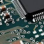
A PCB (Printed Circuit Board) is a board, typically made of non-conductive FR-4 glass epoxy and coated with copper patterns that electrically connect points on the PCB together through traces and pads. The electrical signal passed though PCBs allows power to be directed among a wide range of electrical components according to a desired electronic circuit design. (1,2) When used in discussions of e-waste, the PCB often refers to the board, copper pattern, and all of the components assembled onto the board.
How many PCBs are there?
PCB industries have been seeing modest growth since 2013 although some fall back has been observed in recent years. Worldwide PCB manufacturing amounts to a market worth over $60 billion, while assembly of PCBs into working electronics amounts to over $2,000 billion every year. In recent years, PCBs containing lead (Pb) based solder have dropped to less than 25% of overall PCB production.
Characteristics: High heat sinking, electromagnetic shielding, and high mechanical properties, good processing performance.
Usage: Power Admixture IC (HIC).
1. Audio Equipment: Input and output amplifier, balanced amplifier, audio amplifier; Pre-amplifier and Power amplifiers ect;
2. Power Equipment: Switching regulator `DC / AC converter and SW regulator ect;
3. Telecommunications electronic equipment: High-frequency electrical filter, increases device and transmitter circuit;
4. Office automative equipment: Elector motor drive and so on;
5. Cars: Electronic regulator. Electronic Igniter and power controller;
6. The computer: CPU board. Floppy disk drive devices and power installation;
7. Power Modules: Converter and power rectifier bridg
Product Tags:metal core printed circuit boards prototype circuit board
What are PCB’s Composed of?
A PCB is composed of many layers of different materials, which are laminated together with heat and adhesive. The materials starting from the base of the PCB include a substrate usually made up of FR-4 or fiberglass. Next is a layer of copper which is then laminated to the substrate. These layers may repeat depending on how complex and think the PCB is. The layer above the final layer of copper is known as solder mask which helps insulate the copper from other traces of metal, this layer also gives the PCB its green color. The upper layer of the PCB is the silkscreen which consists of letters, number and symbols which allow for better assembly and understanding of the PCB. Assembled onto the PCB are resistors, capacitors, transistors, integrated circuits, switches, and a variety of other electronic components that make the PCB heterogenous and complicated to recycle and dispose of in an efficient and safe way.
Are PCBs dangerous?
PCB’s can cause a variety of adverse health affects if not disposed of or recycled correctly. Ironically, the PCB becomes a more serious hazard to human health and environment when it is recycled without proper regulation and oversight as opposed to simply dumping it into a landfill. Attempts to shred, dismantle, and burn PCBs during recycling, and to extract precious metals from these electronics during recycling often lead to releases of a variety of toxins in air, soil, and water. Improper burning and shredding releases toxic fumes as well as dangerous particles into the air which depending on their chemistry and size can travel many miles from their point of origin. Treating PCBs to extract precious metals and other valuable materials can release acids and toxins into surface water ways and nearby soils. Toxins released through improper recycling of PCBs can range from heavy metals including lead, cadmium, and mercury to the most toxic substances on earth: dioxins and furans.
You did have a problem where the thermal resistance from the junction specifically to the larger circuit board and surfaces that would shed the heat into the environment was too high, so the component overheated. Either the heat couldn't spread out to the rest of the dissipating surface fast enough, or it could, but there wasn't enough surface to dissipate it into the environment quickly enough. You've addressed both possibilities by giving a low impedance thermal path from the LM7805 to the heatsink, which itself provides more surface area and lots of extra places for heat to escape.
The enclosure, circuit board, etc. will of course still get warm eventually. Just like electrical current, it follows all paths proportional to the resistance. By providing less total resistance, the LM7805 as a thermal 'current' source need not get quite so hot, and the other paths are splitting the wattage ('current') between them, and the lowest resistance path (the heatsink) will get proportionally hotter. You're keeping everything else at a lower temperature by providing a preferential thermal path through the heatsink. But everything else is still going to help, and still going to warm up, to a greater or lesser degree.
So, to answer your specific bullet point questions: You don't need to measure the thermal resistance of the junction to bottom pad, and knowing it is not useful information. It is not going to change anything, and you can't really improve it beyond what you have anyway.
Metal Core PCB Fabrication includes the design and production of printed circuit boards (PCB's) with a metal core, intended for use with LED-based Solid State Lighting and other applications where heat dissipation is required.
Benefits of Metal Core PCB Fabrication
Metal Core PCB Fabrication presents a host of beneficial features for a variety of applications. A lower thermal resistance can be achieved as a result of MCPCB's which incorporate a dielectric polymer layer together with a high thermal conductivity level.
Metal Core PCB Fabrication produces a product that transfers heat up to nine times more rapidly than a typical FR4 PCB. The laminates in MCPCB's dissipate heat which ensures that components which generate heat will remain cooler. This leads to a longer operating life as well as maximized performance for such components.
Applications of Metal Core PCB Fabrication
With the adoption of new technologies, there are many more applications for Metal Core PCB Fabrication. This technology is ideal for applications where components generate a large amount of heat and have difficulty being cooled using conventional fans and other cooling methods. In Solid State Lighting, MCPCB's help achieve a higher level of illumination with fewer LED's required to produce it.
Copper clad PCB is composed of special ceramic powder and epoxy filled polymer composition, with small thermal resistance (0.175), good viscoelastic properties and anti-thermal aging ability , could withstand the mechanical and thermal stress. Copper clad PCB metal substrate is a copper substrate, with a high thermal conductivity, usually is copper (copper could provide better thermal conductivity), which is suitable for drilling, punching and cutting and other conventional machining.
Copper clad PCB applications:
1. Audio equipment: input, output amplifiers, balanced amplifiers, audio amplifiers, preamplifiers, power amplifiers, speakers…
2. Power supply: industrial power equipment, switching regulator, DC / AC converter, SW regulator…
3. Communication electronic equipment: high-frequency amplifier, filter appliances, transmitter circuits…
4. Office automation equipment: motor drives…
5. Car: Electronic regulator, ignition, power controllers, motorcycle ignition…
6. Computer: CPU boards, floppy disk drives, power supply devices…
7. Power module: power supply modules, inverters, solid state relays, power rectifier bridges…
The use of aluminum plate:
1. Audio equipment: input, output amplifier, balanced amplifiers, audio amplifiers, preamplifiers, power amplifiers and so on.
2. Power Supply: Switching regulator `DC / AC converter` SW Regulator and so on.
3. Communication electronics: high-frequency amplifier filter appliance `` transmitter circuit.
4. Office automation equipment: motor drives.
5. Automotive: ignition electronic regulator `` power controller.
6. Computer: CPU board `` floppy disk drive power devices.
7. Power Modules: Inverters `` solid-state relay power rectifier bridges.
For furhter information, please feel free to contact us, www.pcbsino.com