High power supply equipment Aluminum mcpcb aplication
China PCB Manufacturing, Shenzhen PCB Manufacturer, Making Circuit boards
PCB Contract manufacturer, PCB Fabrication, Turnkey assembly services
Buy Print circuit board, customer: /USA/UK/Canada/South Africa...
PCB Supplier Shenzhen, China, PCB Manufacturer, Turnkey services
-
PCBSINO is the Top 5 PCB manufacturer company in China.
PCBSINO do rapid Prototype within 24 hours. our rigid PCB like MCPCB and Rogers PCB, FR4, High TG FR4, Rogers 4003, 4350,Al Aluminum metal Core MCPCB, Al2O3 Ceramic,Taconic,Halogen Free material, CEM-3, Fr2, CEM-1, CEM-2, 94VO, Rogers HF material, Polymide, etc.
PCBSINO making many type electronic product for our customer, Our turkey services team can source original components part for your project(Digikey/Mouser/RS...), senior Electronic engineer will follow each step of the production to solve any PCB problem and our team will do final function test in PCB house.
Express PCB |
|
Rigid PCB Rapid Prototype,24 hours |
| Fr4 PCB |
|
prototype Lower to 15USD ! |
| Rapid Prototype |
|
Fr4 Rigid PCB Rapid Prototype China, |
MCPCB |
|
MCPCB Manufacturer China, Shenzhen |
| Aluminum PCB: |
|
Aluminum Metal Core PCB manufacturing, Fabrication |
| Aluminum PCB: |
|
single side, double side MCPCB, 0.5-5mm or more |
Rogers 4350B |
|
Rogers 4350,Rogers 4003 Manufacturing |
| Rogers 4350B |
|
Rogers 4350B,4003C PCB Manufacturer |
| Ro4350B |
|
Rogers High Frequency PCB Manufaturing China |
Turnkey Services |
|
Turnkey PCB Assembly Services, |
| Turnkey services |
|
Print circuit board Manufacturing, Turnkey Services |
| Turnkey Assembly |
|
Through Hole PCB components wave soldering Assembly |
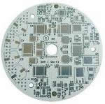
High power supply equipment Aluminum mcpcb aplication
-
High power supply equipment Aluminum mcpcb aplication
Among all Metal core PCBs (aka MCPCBs, known for their ability to provide effective thermal dissipation for electronic products), Aluminum PCBs is the most common type - the base material consists of aluminum core with standard FR4. It features a thermal clad layer that dissipates heat in a highly efficient manner, while cooling components and increasing the overall performance of the products. Currently, Aluminum Backed PCBs is regarded as the solution to high power and tight tolerance applications.
PCBCart: An Experienced MCPCB Manufacturer
Circuitech has been producing Metal base PCBs for over a decade. Although originally envisioned for use in the power-supply industry these substrates are now most widely used in High Brightness LED products and LED TV products. There are many names for these products; Aluminum base, Metal clad(MCPCB), Insulated Metal Substrate(IMS or IMPCB), Thermally conductive PCBs, etc… but they all mean the same thing. A thin layer of thermally conductive but electrically insulating dielectric is laminated between a metal base and a copper foil. The copper foil is etched into the desired circuit pattern and the metal base draws heat away from this circuit through the thin dielectric.
The heat dissipation afforded by this construction is dramatically superior to standard FR-4 constructions. The dielectrics used are typically 5 to 10 times as thermally conductive as conventional epoxy-glass and a tenth of the thickness resulting in thermal transfer exponentially more efficient than a conventional rigid PCB. This is so effective that lower copper weights than suggested by the IPC heat-rise charts can be used.
Which LEDs are suitable for Direct thermal path MCPCB?
Follow is the list,please enquiry for other.
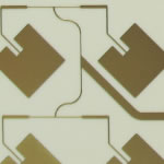
COB MCPCB, known as "Chip-On-Board" Metal Core PCB, is a type of MCPCB used in thermoelectric separation application. By using COB MCPCB, the micro-chip (also known as "die") directly touch the metal core where the heat dissipate, and electrically interconnect the trace of circuit board (wire-bonding) so that power supply can be provided.
In normal MCPCB, there's a dielectric layer between trace copper and metal core, and the thermal conductivity is limited by that dielectric layers, so value can only be 1~3 W/m.K. But using COB MCPCB, there's no such dielectric layer because chip (die) direct touch the metal core, so thermal conductivity value of COB MCPCB will be almost the same one of metal core material itself. The normal material of metal core is aluminum, so thermal conduviity of COB MCPCB is more than 200W/m.K.
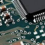
Metal Core PCB use a base metal material as the heat spreader portion of the circuit board. Base metals in the MCPCB are used as an alternative to FR4 boards for the ability to dissipate heat away from critical board components and to less crucial areas such as the metal heatsink backing or metallic core.
Generally speaking, aluminum is the most economic option considering thermal conductivity, rigidness, and cost. Therefore, the base/core material of normal Metal Core PCB are made of aluminum. In our company, if not special request, or notes, the metal core refer will be aluminum, then MCPCB will means Aluminum Core PCB. If you need Copper Core PCB, Steel Core PCB, or Stainless steel core PCB, you should add special notes in drawing.
These PCB are widely used in consumer electronics, LED lighting, telecommunication, computer application, industrial control, automobile etc.
Aluminum-based PCB including: LED aluminum pcb, 1.5m supper long aluminum pcb, aluminum pcb with counterbore holes and blind vias, 3oz/4oz heavy copper aluminum pcb ect.
Our featured products and application:
1, Thermoelectric separation copper-based pcb: 150W-300W high power miner lamp and streetlight.
2, COB silver mirror aluminum pcb: after assembly, lights reflectivity up to 98%, luminous efficiency up to 120 LM.
3, COB Silver plated pcb: 3W、5W、7W bulb light and spotlight etc.
4, 1.5m supper long aluminum pcb: factory is equipped with full set of automatic production line of 1.5m supper led tube aluminum pcb, can mass production.
5, Power supply aluminum pcb: factory use Korea Doo Shanlv substrate material aluminum as substrate material, can withstand 6.0KV voltage, widely used in equipment power supply and automatic products.
6, Ceramic-based pcb: thermal conductivity about 26W, withstand high voltage to 8000-10000V.
Our UL(E465880)/Rohs standards insure quality assemblies from start to finish. Whether it's a simple custom product or a complex turnkey production run, JHD PCB will adhere to the highest quality standards.
Capable
JHD PCB offers the latest in assembly capabilities and qualifications insuring that quality is built into every product we produce.
Experience
When it comes to your build you want a partner you can depend on. Our management team has over 8years of combined industry knowledge. Our engineering team has over 5 years experience.
Protecting your interests
Protecting your Intellectual Property is job one! Our staff of trained professionals are all working under a strict confidentiality contract and treat your important documentation as they would their own.
Flexibility
JHD PCB prides ourselves on our ability to custom tailor programs around our customers' needs. JHD PCB takes time to listen to your unique business needs and then set out to surpass them.
Purchase Tips
a. If you want to purchase our PCB, you should provide a formal Gerber files or *.pcb file or something like that.
b. If you want to purchase by large quantity, please ask Mr.Hank.
c. If you want to purchase the PCBA, you should provide the Gerber files, *.pcb file , BOM list etc.
d. If you want to reproduce some exsited PCB board for you, please first provide very clear pictures , then if you are satisfied with our estimate quotation, then send us the real thing, so we can clone it for you.
e. If none of the above can help you, please contact us directly by Skype, QQ or Email. We are very glad to answer the questions you ask, your satisfaction is our final destination.
Details:
1) Fast PCB with in 12 hours, 24 hours and 48 hours are available.
2) No MOQ for PCB and PCBA and FPC
3) Boards are RoHS compliant with UL(E465880)
4) Engineers with over 10 years of working experience can offer you professional suggestions
5) Factory production Capability of 30000 sqm/month
6) Quality inspection standard: IPC-6012 Class II
7) Base material: FR4, Hi-tg FR4, Aluminum, High frequency (Rogers, Taconic, F4B, Arlon etc.), PI, PET
Our Advantages:
Your best source to PCB & PCBA
1) Every board is to IPC Class II or higher standard
2) All boards are UL approved and made in ISO-9001 certified facilities
3) 100% tested (flying probe or E-test)
4) PCB Design Rule Check with no extra cost
5) Impedence control test
6) Free panelizing
7) Special price/service package for partners
8)professional engineering support. We work with customers closely to ensure the boards are standards compliant.
9) On time delivery
10) No minimum/maximum order
11) Worldwide shipping
With the aim of"Think more for clients, do more for clients, quality as a basis, service first", Shuo Qiang Electronics carry out resources, process and departments integration to make clients really enjoy fast, excellent and effective service. Adhere to the ISO9000 standard and the spirit of perseverance, all the Shuo Qiang people participate in quality improvement, company absorb the latest international technology and improve product quality constantly, to meet customer demand.
Advantage of MCPCB
From the range of Metal Core PCBs aka MCPCB, Aluminium PCBs are one the most preferred and commonly used MCPCB. The specialty of MCBPC lies in its capacity to provide efficient thermal dissipation for electronic products.
Aluminium PCB consists of a base aluminium core with standard FR4. The main feature of Aluminum PCB is its thermal clad layer that dissipates heat in an efficient manner. This feature cools the components and increases the overall performance of the products. Aluminum backed PCBs are the preferred choice for high power applications that have tight tolerance.
SoonEasy – A leading MCPCB manufacturer of China:
SoonEasy acclaims over 10 years of experience as an Aluminium PCB manufacturer and supplier. Our aluminium Printed Circuit Boards are used in a wide range of products including LED lighting, power equipment and automotive systems. Our high tech manufacturing facilities has automation for circuit photos. The strict quality control and testing ensures that our delivered goods are of supreme quality standards.
heat dissipation
Some LEDs dissipate between 2-5W of heat and failures occur when the heat from a LED is not properly removed; a LED’s light output is reduced as well as degradation when the heat remains stagnant in the LED package. The purpose of a MCPCB is to efficiently remove the heat from all topical IC’s (not just LEDs).
COB process consists of three main categories to perform when manufacturing the Chip-on-Board:
1st: 'die mount or die attach';
2nd: 'wire bonding';
3rd: 'the encapsulation of die wires'.
By using wire bonding & epoxy packaging then directly embedded on MCPCB, this practice can extend the lifespan of LED and unified light emission.
According to process and material, COB MCPCB applications can be categorized into two types: Mirror Aluminum and silver or gold platting aluminum, or silver plating mirror aluminum PCB.
Structure of COB MCPCB
Cree XP-G/E/C/G2
Cree XML/XML2
Cree MTG/MTG2
Cree MK-R
Cree XTE
Cree XBD
CREE XHP70 N4 LED
Bridgelux SM4
Luxeon Rebel
Luxeon M
Luxeon-T
LEDEngin LZC/LZP
Nichia N219A/N219B
Seoul Z5P/Z5M
Osram Oslon SSL
Samsung 3535
LG Innotek 3535
Advantages to the user:
The 0.3 mm thick copper layer permits higher current loading for the same conductor width. Assuming the same copper cross-section, the conductor needs to be only 12% of that of a normal printed circuit board
Excellent thermal conductivity provides the possibility of very close packaging of the chips. This translates into more power per unit of volume and improved reliability of systems and equipment
The high insulation voltage allows the use of thin dielectric material (alumina) for improved thermal dissipation for high voltage applications.
DBC ceramic is the basis for the "chip-on-board" technology which represents the packaging trend for the future
DBC ceramic substrates are the base materials of the future for both the construction and the interconnection techniques of electronic circuits. Therefore DBC is used in our daily environment, such as:
Power hybrids and power control circuits
Power semiconductor modules
Smartpower building blocks
Solid state relays
High frequency switch mode power supplies (SMPS)
Electronic heating devices
Building blocks for automobile electronics, as well as aerospace technology
Search Aluminum PCB Advanced Circuits Specification
Among all MCPCBs (Metal Core PCB, known for its ability providing effective thermal dissipation for electronic products), Aluminum PCB, the most common type and the basic material, consists of aluminum core with standard FR4. It features a thermal clad layer that dissipates heat in a highly efficient manner, while cooling components and increasing the overall performance of the products. Currently, Aluminum Backed PCB tends to solve problems of high power and tight tolerance applications.
An Experienced MCPCB Manufacturer
By Dave Basista, Product Manager – Heavy Copper/EXTREME Copper/PowerLink
Epec Engineered Technologies
Standard printed circuit boards, whether double-sided or multilayer, are manufactured using a combination of copper etching and plating processes. Circuit layers start as thin sheets of copper foil (generally 0.5 oz/ft2 to 2 oz/ft2) that are etched to remove unwanted copper, and plated to add copper thickness to planes, traces, pads and plated-through-holes. All of the circuit layers are laminated into a complete package using an epoxy-based substrate, such as FR4 or polyimide.
Boards incorporating heavy copper circuits are produced in exactly the same way, albeit with specialized etching and plating techniques, such as high-speed/step plating and differential etching. Historically, heavy copper features were formed entirely by etching thick copper clad laminated board material, causing uneven trace sidewalls and unacceptable undercutting. Advances in plating technology have allowed heavy copper features to be formed with a combination of plating and etching, resulting in straight sidewalls and negligible undercut.
Plating of a heavy copper circuit enables the board fabricator to increase the amount of copper thickness in plated holes and via sidewalls. It's now possible to mix heavy copper with standard features on a single board, also known as PowerLink. Advantages include reduced layer count, low impedance power distribution, smaller footprints and potential cost savings. Normally, high-current/high-power circuits and their control circuits were produced separately on separate boards. Heavy copper plating makes it possible to integrate high-current circuits and control circuits to realize a highly dense yet simple board structure.
The heavy copper features can be seamlessly connected to standard circuits. Heavy copper and standard features can be placed with minimal restriction provided the designer and fabricator discuss manufacturing tolerances and abilities prior to final design (Figure 2).
Figure 2. 2oz features connect control circuits while 20oz features carry high current loads.
As designers strive to obtain maximum value and performance from their projects, printed circuits are becoming more complex and are driven to higher power densities. Miniaturization, use of power components, extreme environmental conditions and high-current requirements increase the importance of thermal management. The higher losses in the form of heat, that's often generated in the operation of electronics, has to be dissipated from its source and radiated to the environment; otherwise, the components could overheat and failures may result. However, heavy copper circuits can help by reducing the I2R losses and by conducting heat away from valuable components, reducing failure rates dramatically.
In order to achieve proper heat dissipation from heat sources in and on the surface of a circuit board, heatsinks are employed. The purpose of any heatsink is to dissipate heat away from the source of generation by conduction and emit this heat by convection to the environment. The heat source on one side of the board (or internal heat sources) is connected by copper vias (sometimes called "heat vias") to a large bare copper area on the other side of the board.
Generally, classical heatsinks are bonded to this bare copper surface by means of a thermally conductive adhesive or in some cases, are riveted or bolted. Most heatsinks are made of either copper or aluminum.
The assembly process required for classical heatsinks consists of three labor-intensive and costly steps. The time and work required to complete this process is significant, and the results are inferior to a mechanically automated process. In contrast, built-in heatsinks are created during the printed circuit board manufacturing process and require no additional assembly. Heavy copper circuit technology makes this possible. This technology allows the addition of thick copper heatsinks virtually anywhere on the outer surfaces of a board. The heatsinks are electroplated on the surface and thus connected to the heat conducting vias without any interfaces that impede thermal conductivity.
Another benefit is the added copper plating in the heat vias, which reduces the thermal resistance of the board design, realizing that they can expect the same degree of accuracy and repeatability inherent in PCB manufacturing. Because planar windings are actually flat conductive traces formed on copper clad laminate, they improve the overall current density compared to cylindrical wire conductors. This benefit is due to minimization of skin effect and higher current-carrying efficiency.
On-board planars achieve excellent primary-to-secondary and secondary-to-secondary dielectric isolation because the same dielectric material is used between all layers, ensuring complete encapsulation of all windings. In addition, primary windings can be spilt so that the secondary windings are sandwiched between the primaries, achieving low leakage inductance. Standard PCB lamination techniques, using a choice of a variety of epoxy resins, can safely sandwich up to 50 layers of copper windings as thick as 10 oz/ft2.
During the manufacture of heavy copper circuits, we are usually dealing with significant plating thicknesses; therefore, allowances must be made in defining trace separations and pad sizes. For this reason, designers are advised to have the board fabricator on board early in the design process. Epec Engineered Technologies has developed a set of design guidelines for heavy copper circuits that give designers a basic overview of what is required.
Current Carrying Capacity and Temperature Rise
The amount of current a copper circuit can safely carry depends on how much heat rise a project can withstand, since heat rise and current flow are related. When current flows along a trace, there is an I2R (power loss) that results in localized heating. The trace cools by conduction (into neighboring materials) and convection (into the environment). Therefore, to find the maximum current a trace can safely carry, we must find a way to estimate the heat rise associated with the applied current. An ideal situation would be to reach a stable operating temperature where the rate of heating equals the rate of cooling. An IPC formula can be used to model this event.
An increasing number of power electronics products are taking advantage of a growing trend in the printed circuit board industry: Heavy Copper and EXTREME Copper Printed Circuit Boards.
Most commercially available PCBs are manufactured for low-voltage/low power applications, with copper traces/planes made up of copper weights ranging from 1/2 oz/ft2 to 3 oz/ft2. A heavy copper circuit is manufactured with copper weights anywhere between 4 oz/ft2 to 20 oz/ft2. Copper weights above 20 oz/ft2 and up to 200 oz/ft2 are also possible and are referred to as EXTREME Copper. Our discussion will focus primarily on Heavy Copper.
The construction of a heavy copper circuit endows a board with benefits such as:
Increased endurance to thermal strains.
Increased current carrying capacity.
Increased mechanical strength at connector sites and in PTH holes.
Use of exotic materials to their full potential (i.e., high temperature) without circuit failure.
Reduced product size by incorporating multiple copper weights on the same layer of circuitry (see Figure 1).
Heavy copper plated vias carry higher current through the board and help to transfer heat to an external heatsink.
On-board heatsinks directly plated onto the board surface using up to 120-oz copper planes.
On-board high-power-density planar transformers
Flying has been offering MCPCB manufacturing service for over ten years. Our full features about aluminum circuit boards own high capabilities and value-added options including Free DFM Check allowing you to get high-quality aluminum PCBs done on budget. Aluminum PCBs printed by us are widely used for LED lighting, power equipment and automotive systems.
Some of our Aluminum Core materials:
Item Performance Index (Measured value)
Peeling strength (n/mm) 1.8
Insulation resistance (ω) >1*10 g
Breakdown voltage (vdc) >2 k
Soakable soldering (°C/m) 280°C / 260°C, 1 min, no bubble & delamination
Thermal conductivity (ω/m-k) >0.8
Thermal resistance (°C/ω) < 1.2
Combustibility fv-o
Dielectric constant (1mhz) 4
Dielectric loss angle (tangent) 0.03
Applications
IGBT
High-Frequency Switching Power Supply
Automotive
Aerospace
Solar Cell Component
Power Supply for Telecommunication
Laser Systems
The newly developed DBC technologies of the liquid cooled and the partial discharge free substrates have a great potential to expand further application fields of DBC substrates as well as high power semiconductor modules in the near future.
Although Power Converters and LEDs are the largest users of these products, Automotive and RF companies are also looking to take advantage of the benefits of these constructions. A single layer construction is the simplest, most thermally conductive and most cost effective construction. Designs with higher component counts may not have room for all the required routing on a single layer. In this case a two layer design is required. A thin sheet of dielectric, typically around .006” thick, is drilled, plated and etched much like a standard double sided printed circuit board. The sheet is then laminated using thermally conductive bonding material to the metal base. This extra routing layer results in components farther away from the heat-sink and reduced heat transfer so this construction is recommended only when necessary. However, Circuitech is experiencing 4 layer structure required and successfully production for higher function construction layout.
PCBCart has been offering aluminum PCB manufacturing services for over ten years. Our full feature aluminum circuit boards making capabilities and value-added options including Free DFM Check allow you to get high-quality aluminum PCBs done within budget. Aluminum PCBs printed by us are widely used for LED lighting, power equipment and automotive systems.
For furhter information, please feel free to contact us, www.pcbsino.com