Pulse motor Aluminum mcpcb aplication
China PCB Manufacturing, Shenzhen PCB Manufacturer, Making Circuit boards
PCB Contract manufacturer, PCB Fabrication, Turnkey assembly services
Buy Print circuit board, customer: /USA/UK/Canada/South Africa...
PCB Supplier Shenzhen, China, PCB Manufacturer, Turnkey services
-
PCBSINO is the Top 5 PCB manufacturer company in China.
PCBSINO do rapid Prototype within 24 hours. our rigid PCB like MCPCB and Rogers PCB, FR4, High TG FR4, Rogers 4003, 4350,Al Aluminum metal Core MCPCB, Al2O3 Ceramic,Taconic,Halogen Free material, CEM-3, Fr2, CEM-1, CEM-2, 94VO, Rogers HF material, Polymide, etc.
PCBSINO making many type electronic product for our customer, Our turkey services team can source original components part for your project(Digikey/Mouser/RS...), senior Electronic engineer will follow each step of the production to solve any PCB problem and our team will do final function test in PCB house.
Express PCB |
|
Rigid PCB Rapid Prototype,24 hours |
| Fr4 PCB |
|
prototype Lower to 15USD ! |
| Rapid Prototype |
|
Fr4 Rigid PCB Rapid Prototype China, |
MCPCB |
|
MCPCB Manufacturer China, Shenzhen |
| Aluminum PCB: |
|
Aluminum Metal Core PCB manufacturing, Fabrication |
| Aluminum PCB: |
|
single side, double side MCPCB, 0.5-5mm or more |
Rogers 4350B |
|
Rogers 4350,Rogers 4003 Manufacturing |
| Rogers 4350B |
|
Rogers 4350B,4003C PCB Manufacturer |
| Ro4350B |
|
Rogers High Frequency PCB Manufaturing China |
Turnkey Services |
|
Turnkey PCB Assembly Services, |
| Turnkey services |
|
Print circuit board Manufacturing, Turnkey Services |
| Turnkey Assembly |
|
Through Hole PCB components wave soldering Assembly |
Pulse motor Aluminum mcpcb aplication
-
Pulse motor Aluminum mcpcb aplication
Using laminates on an IMS (Insulated Metal Substrate) in the form of an aluminium core to manufacture printed circuit boards called MCPCB (Metal Core Printed Circuit Boards) can overcome these problems, or at least greatly reduce them.
Aluminium core laminates are characterised by high thermal conductivity, a parameter designated as TC. The standard IMS laminate offered by PCB manufacturers, including Techno-Service S.A. has the TC at 2 W/mK. There are also commercial material with the TC of 2 to 5 W/mK. The TC of the typical FR4 laminate is one order lower (0.3 W/mK). Moreover, aluminium core laminates are mechanically stronger (more rigid) at the same material thickness and have a thermal expansion lower than FR4.
These advantages make aluminium cores usable as a substrate for PCBs and heat sinks for dissipation of the heat from the assembled SMD components. The benefits of applying IMS laminates, when compared with the traditional FR4, are shown in Fig. 1 that depicts an identical device design assembled in both substrate technologies. The FR4 based device (see Fig. 1a) is much larger and heavier due to the large radiator required for the THT encapsulated power components. It also needs a larger and stronger enclosure. Its production is certainly less cost-effective than the MCPCB version shown in Fig. 1b.
Single-sided MCPCBs are currently most popular on the market. The MCPCB cross-section is shown in Fig. 2. The laminate top side features a traditional conductor layer of copper foil with the thickness analogical to that in FR4 (i.e. 8 μm, 35 μm, 70 μm, 105 μm). The conductive copper layer is separated from the aluminium core by a special dielectric (film) with a high thermal conductivity.
metal core pcb implies that the core material is made of metal and not FR4 used in circuit boards, the common metals used are aluminum copper and steel alloy, aluminum processes good dissipating and head transfer capabilities although copper performs better than aluminum, aluminum is preferred since it is cheaper steel have lower thermal conductivity than copper and alumium but is more rigig as compared to copper and aluminum, depending on your application you may choose to get a metal core pcb made of any of three metals
the most common and pocket friendy option is aluminum as such most metal core pcb have aluminum cores, traditional pcbs were made of FR4 metal core pcb have replaced them since they are more efficient at dissipating heat from the circuit components, the termally conductive dielectrinc layer is responsible for heat dissipation. this layer acts as a heat bridge between components of the integrated circuit and the metal backing plate, heat moves through the metal core from the package on to an added heat sink. if the heat is not transferred by topital head sinks on the fr4 board, then it remains stagnant, leds usually have steel core pcbs but a few are made from steel core pcb
metal core pcb have the following advantages
thermal expansion
aluminum and copper expand and contract when exposed to different temperatures this ensure that the metal core pcbs do not get damaged with a change in operatiing temperatures of appliances and electronic gadgets
Aluminum substrate (metal core base such as aluminum base, copper base,and Iron base) has better heat conductivity, Electrical insulation performance and Mechanical processing performance. And it can bear higher current and voltage with the same line width, gap and board thickness compare the FR4 material. Its thermal conductivity can rank up 2.0 with the Breakdown voltage 4500V, among them Aluminum base is the most popular.
● Easy for surface mount technology
● Thermal diffusion is very effective in circuit design
● Reduce operating temperature, improve product power density and reliability to extend the product life
● Narrow product volume, lower hardware and assembly costse.Replacing the fragile ceramic substrate to obtain better mechanical endurance
Capability:
Material: Aluminum base, copper base, iron base
Surface finish: HASL,ENIG, OSP, Plated Tin, Plated silver, Immersion Tin
Surface finish thickness: Ni 4-6um, Au:0.04-0.5um
Single Layer Metal Core PCB
A simple layer single sided MCPCB consists of a metal base (usually aluminum, or copper alloy), Dielectric (non-conducting) Layer, Copper Circuit Layer, IC components and solder mask.
The prepreg dielectric provides excellent heat transfer from the foil and components to the base plate, while maintaining excellent electrical isolation. The base aluminum/copper plate gives the single-sided substrate mechanical integrity, and distributes and transfers the heat to a heat sink, mounting surface or directly to the ambient air.
The Single-Layer MCPCB can be used with surface mount and chip & wire components, and provides much lower thermal resistance than FR4 PWB. The metal core provides lower cost than ceramic substrates, and allows much larger areas than ceramic substrates.
Double Layers Metal Core PCB
Double layers MCPCB is consisting of two layers of copper conductor, put them on same side of metal core (usually aluminum, copper or iron alloy). The metal base is on the bottom of whole MCPCB, which is different from double sided MCPCB(the two copper layers were put on the each side of metal core respectively), and you can only populate SMD on top side.
Different with Single layer MCPCB, 2 layers MCPCB requires an additional pressing step to laminate the imaged thermal conductive laminate and metal core (also known as metal base) together.
Compared with normal FR4, this sturcture need more technology and experience on laminating of two layers together with metal core.
The processing steps of the MCPCB with the metal base embedded in the PCB are comparatively complex as hole plugging is required after primary drilling on the metal base in order to isolate it from the circuitry.
Double Sided Metal Core PCB
It also has same two layers of copper conductor like Double layers MCPCB, but the metal core is in the middle of two conductor, so there're conductors (trace) on both sides of metal core, and were connected to each other by Vias. So we named it "Double sided MCPCB", and you can populated SMD on both top and bottom.
Different with Single layer MCPCB, double sided MCPCB also requires an additional pressing step to laminate the imaged thermal conductive laminate and metal core (also known as metal base) together. But sometimes, some raw Metal Clad material vendor will supply board material which already laminated.
Compared with normal FR4, this sturcture need more technology and experience on laminating of two layers together with metal core.
Multi Layers Metal Core PCB
Just like FR4 PCB, we can also make boards with more than 2 layers of traces and we named it "Multi Layers MCPCB". The structure is similar with FR4 Multi Layers, but it much more complex to make.
You can populated more components on the boards, put signal and ground layer into seperated layers, to achieve better performance in electrical performance.
Compared with normal FR4, this sturcture need more technology and experience on laminating of more than two layers together with metal core and the cost is much higher than 2 layers MCPCBor double sided MCPCB.
Application of MCPCB
LED lights:High-current LED, Spotlight, high-current PCB
Industrial power equipment:High-power transistors, transistor arrays, push-pull or totem pole output circuit (to tem pole), solid-state relay, pulse motor driver, the engine Computing amplifiers (Operational amplifier for serro-motor), pole-changing device (Inverter)
Cars:firing implement, power regulator, exchange converters, power controllers, variable optical system
Power:voltage regulator series, switching regulator, DC-DC converters
Single Layer Metal Core PCB
A simple layer single sided MCPCB consists of a metal base (usually aluminum, or copper alloy), Dielectric (non-conducting) Layer, Copper Circuit Layer, IC components and solder mask.
The prepreg dielectric provides excellent heat transfer from the foil and components to the base plate, while maintaining excellent electrical isolation. The base aluminum/copper plate gives the single-sided substrate mechanical integrity, and distributes and transfers the heat to a heat sink, mounting surface or directly to the ambient air.
The Single-Layer MCPCB can be used with surface mount and chip & wire components, and provides much lower thermal resistance than FR4 PWB. The metal core provides lower cost than ceramic substrates, and allows much larger areas than ceramic substrates.
Double Layers Metal Core PCB
Double layers MCPCB is consisting of two layers of copper conductor, put them on same side of metal core (usually aluminum, copper or iron alloy). The metal base is on the bottom of whole MCPCB, which is different from double sided MCPCB(the two copper layers were put on the each side of metal core respectively), and you can only populate SMD on top side.
Different with Single layer MCPCB, 2 layers MCPCB requires an additional pressing step to laminate the imaged thermal conductive laminate and metal core (also known as metal base) together.
Compared with normal FR4, this sturcture need more technology and experience on laminating of two layers together with metal core.
The processing steps of the MCPCB with the metal base embedded in the PCB are comparatively complex as hole plugging is required after primary drilling on the metal base in order to isolate it from the circuitry.
Double Sided Metal Core PCB
It also has same two layers of copper conductor like Double layers MCPCB, but the metal core is in the middle of two conductor, so there're conductors (trace) on both sides of metal core, and were connected to each other by Vias. So we named it "Double sided MCPCB", and you can populated SMD on both top and bottom.
Different with Single layer MCPCB, double sided MCPCB also requires an additional pressing step to laminate the imaged thermal conductive laminate and metal core (also known as metal base) together. But sometimes, some raw Metal Clad material vendor will supply board material which already laminated.
Compared with normal FR4, this sturcture need more technology and experience on laminating of two layers together with metal core.
Multi Layers Metal Core PCB
Just like FR4 PCB, we can also make boards with more than 2 layers of traces and we named it "Multi Layers MCPCB". The structure is similar with FR4 Multi Layers, but it much more complex to make.
You can populated more components on the boards, put signal and ground layer into seperated layers, to achieve better performance in electrical performance.
Compared with normal FR4, this sturcture need more technology and experience on laminating of more than two layers together with metal core and the cost is much higher than 2 layers MCPCBor double sided MCPCB.
Application of MCPCB
LED lights:High-current LED, Spotlight, high-current PCB
Industrial power equipment:High-power transistors, transistor arrays, push-pull or totem pole output circuit (to tem pole), solid-state relay, pulse motor driver, the engine Computing amplifiers (Operational amplifier for serro-motor), pole-changing device (Inverter)
Cars:firing implement, power regulator, exchange converters, power controllers, variable optical system
Other Specifications: 4 Layer Routing Round Custom Double Sided Metal Core PCB for LED 0.5mm ~ 3.0mm Application of MCPCB LED lights:High-current LED, Spotlight, high-current PCB Industrial power equipment:High-power transistors, transistor arrays, push-pull or totem pole output circuit (to tem pole), solid-state relay, pulse motor driver, the engine Computing amplifiers (Operational amplifier for serro-motor), pole-changing device (Inverter) Cars:firing implement, power regulator, exchange converters, power controllers, variable optical system Power:voltage regulator series, switching regulator, DC-DC converters OA:Printer driver, large electronic display substrate, thermal print head Audio:input - output amplifier, balanced amplifier, pre-shield amplifier, audio amplifier, power amplifier Others:Semiconductor thermal insulation board, IC arrays, resistor arrays, Ics carrier chip, heat sink, solar cell substrates, semiconductor refrigeration device Capability layers:1-4layers Base material: Aluminum/Copper/Iron Alloy Thermal Conductivity (dielectrial layer): 0.8, 1.5, 2.0, 3.0 W/m.K. Withstand voltage:2000-8000V Board Thickness: 0.5mm~3.0mm(0.02"~0.12") Copper thickness: 0.5 OZ, 1.0 OZ, 2.0 OZ, 3.0 OZ, up to 6 OZ Outline: Routing, punching, V-Cut Soldermask: White/Black/Blue/Green/Red ,Taiyo PSR4000 white Legend/Silkscreen Color: Black/White Surface finishing: Immersion Gold, HASL, OSP Max Panel size: 600*1200mm(23.62"*47.24") Packing: Vacuum/Plastic bag Samples L/T: 4~6 Days Single Layer Metal Core PCB A simple layer single sided MCPCB consists of a metal base (usually aluminum, or copper alloy), Dielectric (non-conducting) Layer, Copper Circuit Layer, IC components and solder mask. The prepreg dielectric provides excellent heat transfer from the foil and component
Power:voltage regulator series, switching regulator, DC-DC converters
OA:Printer driver, large electronic display substrate, thermal print head
Audio:input - output amplifier, balanced amplifier, pre-shield amplifier, audio amplifier, power amplifier
Others:Semiconductor thermal insulation board, IC arrays, resistor arrays, Ics carrier chip, heat sink, solar cell substrates, semiconductor refrigeration device
Layer count: single and double sided
Board thickness:0.3-3.0mm
Copper weight: Hoz to 3oz
Maximum size: 1200*480mm
Minimum size:5*5mm
Min track width/gap: 0.1/0.1mm
Hole copper weight:15-25um
Hole position tolerance:+/-0.076mm
Min hole size:0.6mm
Minimum punching hole size: 1.0mm
Silkscreen tolerance:+/-0.1mm
Min solder mask window:0.1mm
Min legend width:0.1mm
Outline tolerance:+/-0.1mm
Wrap and twist:≤0.5%
Single Layer Metal Core PCB
A simple layer single sided MCPCB consists of a metal base ( usually aluminum, or copper alloy) , Dielectric ( non-conducting) Layer, Copper Circuit Layer, IC components and solder mask.
The prepreg dielectric provides excellent heat transfer from the foil and components to the base plate, while maintaining excellent electrical isolation. The base aluminum/ copper plate gives the single-sided substrate mechanical integrity, and distributes and transfers the heat to a heat sink, mounting surface or directly to the ambient air.
The Single-Layer MCPCB can be used with surface mount and chip & wire components, and provides much lower thermal resistance than FR4 PWB. The metal core provides lower cost than ceramic substrates, and allows much larger areas than ceramic substrates.
Double Layers Metal Core PCB
Double layers MCPCB is consisting of two layers of copper conductor, put them on same side of metal core ( usually aluminum, copper or iron alloy) . The metal base is on the bottom of whole MCPCB, which is different from double sided MCPCB( the two copper layers were put on the each side of metal core respectively) , and you can only populate SMD on top side.
Different with Single layer MCPCB, 2 layers MCPCB requires an additional pressing step to laminate the imaged thermal conductive laminate and metal core ( also known as metal base) together.
Compared with normal FR4, this sturcture need more technology and experience on laminating of two layers together with metal core.
The processing steps of the MCPCB with the metal base embedded in the PCB are comparatively complex as hole plugging is required after primary drilling on the metal base in order to isolate it from the circuitry.
Double Sided Metal Core PCB
It also has same two layers of copper conductor like Double layers MCPCB, but the metal core is in the middle of two conductor, so there' re conductors ( trace) on both sides of metal core, and were connected to each other by Vias. So we named it " Double sided MCPCB " , and you can populated SMD on both top and bottom.
Different with Single layer MCPCB, double sided MCPCB also requires an additional pressing step to laminate the imaged thermal conductive laminate and metal core ( also known as metal base) together. But sometimes, some raw Metal Clad material vendor will supply board material which already laminated.
Compared with normal FR4, this sturcture need more technology and experience on laminating of two layers together with metal core.
Multi Layers Metal Core PCB
Just like FR4 PCB, we can also make boards with more than 2 layers of traces and we named it " Multi Layers MCPCB " . The structure is similar with FR4 Multi Layers, but it much more complex to make.
You can populated more components on the boards, put signal and ground layer into seperated layers, to achieve better performance in electrical performance.
Compared with normal FR4, this sturcture need more technology and experience on laminating of more than two layers together with metal core and the cost is much higher than 2 layers MCPCBor double sided MCPCB.
Application of MCPCB
LED lights: High-current LED, Spotlight, high-current PCB
Industrial power equipment: High-power transistors, transistor arrays, push-pull or totem pole output circuit ( to tem pole) , solid-state relay, pulse motor driver, the engine Computing amplifiers ( Operational amplifier for serro-motor) , pole-changing device ( Inverter)
Cars: firing implement, power regulator, exchange converters, power controllers, variable optical system
Power: voltage regulator series, switching regulator, DC-DC converters
OA: Printer driver, large electronic display substrate, thermal print head
Audio: input - output amplifier, balanced amplifier, pre-shield amplifier, audio amplifier, power amplifier
Others: Semiconductor thermal insulation board, IC arrays, resistor arrays, Ics carrier chip, heat sink, solar cell substrates, semiconductor refrigeration device
ability to dissipate heat
light emitting diodes are notorious for giving off a lot of heat, some dissipate between two to 5 watts of heat if this heat is not properly removed, the led fails, stagnant heat also makes leds output go down and it degrades
metal core pcb efficiently remove heat from leds and integrated circuits the IC’s and heat sink are brigdge by the thermally conductive dielectric layer and aluminum base
stability
metal core pcb are more dimensional stable as compared to tradictional circuit boards
metal core pcb can be found in led lights and spotlights these usually have high current industrial equipment like pulse motors also have metal core pcbs, in cars, they can be found in power regulators exchange converters and vehicles firing implement, audio equipment like amplifiers also have metal core pcbs
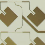
Fig. 2. Build-up of a single-sided aluminium MCPCB and the available thickness values of individual layers.
The dielectric thickness and thermal conductivity determine the TC value and breakdown resistance of the entire laminate. Standard IMS laminates at TC = 2 W/mK feature 125 μm dielectrics which ensure breakdown resistances at singular kV values, which is more than in FR4. The bottom side of the aluminium substrate is coated with a protective foil that keeps the core safe from the damaging action of the chemical solutions applied in PCB manufacturing processes.
The core protective foils is removed at the last production stage. Commercial IMS laminates exist with aluminized cores that are additionally anodised to increase the corrosion resistance of the exposed aluminium face. The added oxide layer inhibits heat dissipation from the core, but the overall reduction of thermal conductivity is small and negligible in the thermal resistance calculations of the circuit for most applications.
Applications
Just like FR4 PCB, we can also make boards with more than 2 layers of traces and we named it "Multi Layers MCPCB". The structure is similar with FR4 Multi Layers, but it much more complex to make.
You can populated more components on the boards, put signal and ground layer into seperated layers, to achieve better performance in electrical performance.
Compared with normal FR4, this sturcture need more technology and experience on laminating of more than two layers together with metal core and the cost is much higher than 2 layers MCPCBor double sided MCPCB.
Application of MCPCB
LED lights:High-current LED, Spotlight, high-current PCB
Industrial power equipment:High-power transistors, transistor arrays, push-pull or totem pole output circuit (to tem pole), solid-state relay, pulse motor driver, the engine Computing amplifiers (Operational amplifier for serro-motor), pole-changing device (Inverter)
Cars:firing implement, power regulator, exchange converters, power controllers, variable optical system
Power:voltage regulator series, switching regulator, DC-DC converters
OA:Printer driver, large electronic display substrate, thermal print head
Audio:input - output amplifier, balanced amplifier, pre-shield amplifier, audio amplifier, power amplifier
Others:Semiconductor thermal insulation board, IC arrays, resistor arrays, Ics carrier chip, heat sink, solar cell substrates, semiconductor refrigeration device
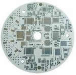
Fig. 3. Examples of MCPCBs produced by Techno-Service.
MCPCBs are popular in modern high power equipment, e.g. pulsed power supply units (inverters) and lamps based on high-output SMD LED arrays. The SMD LED lamps have found general use in lighting applications, the automotive industry (as road lights of motor vehicles) or street signal lights. The laminates for those applications are usually coated with white solder masks that increase light reflectance. Fig. 3 shows examples of MCPCBs for lamps.
For furhter information, please feel free to contact us, www.pcbsino.com