High power SW regulator Aluminum mcpcb aplication
China PCB Manufacturing, Shenzhen PCB Manufacturer, Making Circuit boards
PCB Contract manufacturer, PCB Fabrication, Turnkey assembly services
Buy Print circuit board, customer: /USA/UK/Canada/South Africa...
PCB Supplier Shenzhen, China, PCB Manufacturer, Turnkey services
-
PCBSINO is the Top 5 PCB manufacturer company in China.
PCBSINO do rapid Prototype within 24 hours. our rigid PCB like MCPCB and Rogers PCB, FR4, High TG FR4, Rogers 4003, 4350,Al Aluminum metal Core MCPCB, Al2O3 Ceramic,Taconic,Halogen Free material, CEM-3, Fr2, CEM-1, CEM-2, 94VO, Rogers HF material, Polymide, etc.
PCBSINO making many type electronic product for our customer, Our turkey services team can source original components part for your project(Digikey/Mouser/RS...), senior Electronic engineer will follow each step of the production to solve any PCB problem and our team will do final function test in PCB house.
Express PCB |
|
Rigid PCB Rapid Prototype,24 hours |
| Fr4 PCB |
|
prototype Lower to 15USD ! |
| Rapid Prototype |
|
Fr4 Rigid PCB Rapid Prototype China, |
MCPCB |
|
MCPCB Manufacturer China, Shenzhen |
| Aluminum PCB: |
|
Aluminum Metal Core PCB manufacturing, Fabrication |
| Aluminum PCB: |
|
single side, double side MCPCB, 0.5-5mm or more |
Rogers 4350B |
|
Rogers 4350,Rogers 4003 Manufacturing |
| Rogers 4350B |
|
Rogers 4350B,4003C PCB Manufacturer |
| Ro4350B |
|
Rogers High Frequency PCB Manufaturing China |
Turnkey Services |
|
Turnkey PCB Assembly Services, |
| Turnkey services |
|
Print circuit board Manufacturing, Turnkey Services |
| Turnkey Assembly |
|
Through Hole PCB components wave soldering Assembly |
High power SW regulator Aluminum mcpcb aplication
-
High power SW regulator Aluminum mcpcb aplication
The Mechanisms of Heat Transfer
Heat transfer mechanisms can be grouped into three broad categories:
Conduction. Areas that have more molecular kinetic energy will send their thermal energy to areas that have less molecular energy. This occurs through a direct collision of molecules, known as conduction. In metals, some of the energy transported from one area to another is also carried by conduction-band electrons.
Convection. When heat is generated in an electronic device, it’s transported via conduction to an area
where it is then transferred to a fluid. That process is convection, and the fluid can take the form of a gas such as air or conventional water.
Radiation. All materials give off thermal energy in amounts that are determined by temperature. When the temperatures are uniform, the radiation flux is in in equilibrium between objects, and there is no exchange of thermal energy. This balance changes when temperatures vary and thermal energy is transported from areas of higher temperatures to those of lower temperature.
The Evolution of Printed Circuit Boards
PCBs are kin to the electrical connection systems introduced in the 1850s, in which metal strips or rods connected large electric components installed on wooden bases. Over time, wires connected to screw terminals replaced the metal strips and metal chassis used in place of the wooden bases. While these were certainly important technological advances, the systems were too large to meet the growing need for smaller, more compact designs demanded by products that used circuit boards.
This demand inspired Charles Ducas of the United States to develop a stencil with conductive inks that could “print” electrical paths directly on insulated surfaces. He submitted a patent on the process in 1925, giving birth to the phrases “printed wiring” and “printed circuit.”
1943 saw the development and patenting of a method to etch conductive patterns (circuits) onto a layer of copper foil, which was fused to a non-conductive base material reinforced with glass. The technique, developed by Paul Eisler of the United Kingdom, gained widespread popularity in the 1950s with the advent of transistors for commercial use. Until that time, vacuum tubes and other components were so large that only traditional mounting and wiring methods were required.
Transistors changed everything, however — components shrunk in size considerably, and manufacturers sought to reduce the overall size of their electronic packages by switching to PCBs.
The introduction of through-hole technology and its use in multi-layer PCBs in the 1960s resulted in increased component density and tightly spaced electrical paths, and started a new era in PCB design. In the 1970s, integrated circuit chips become foundational to printed circuit board design.
Aluminum PCB Applications
Aluminum back PCBs are ideal for situations when thermal heat dissipation requirements very high. PCBs clad with aluminum are more effective at directing thermal energy away from printed circuit board components therefore provide better temperature management for PCB designs. Aluminum-backed designs can be as much as ten times more efficient than fiberglass-backed designs when it comes to removing thermal energy from circuit board components. The much higher thermal dissipation rate allows higher power and higher density designs to be implemented.
Aluminum-backed PCBs are used more than ever for applications of high power/high thermal heat dissipation. Although they were originally designed for high power switching supply applications, aluminum-backed printed circuit boards have gained popularity in LED applications, including traffic lights, automotive lighting and general lighting. The use aluminum designs allow the density of LEDs in the PCB design to be higher and for the mounted LEDs to operate at higher currents while staying within specified temperature tolerances.
Aluminum-backed PCBs also allow for decreased safety margins with power LEDs compared to conventional PCB design. Lower operating temperature of the LEDs in a design means the LEDs can operate for longer periods of time before they fail.
SinkPADTM technology has magnitudes higher thermal efficiency than even the very best MCPCB in the market. SinkPADTM MCPCB is available with Aluminum base metal or Copper base metal. Aluminum based SinkPADTM PCB can transfer heat at the rate of 210.0 W/m.K and Copper based SinkPADTM PCB can transfer heat at a rate of 385.0 W/m.k. Conventional MCPCBs have a heat transfer rate of 1-5 W/m.k. The way in which we can accomplish this dramatic improvement is by creating a Direct Thermal Path from the LED to the base metal.
Detailed Product Description
Aluminum PCB, Metal core PCB, LED PCB
Advantage: High Heat dissipation, Electromagnetic Shielding, High Mechanical Strength, Excellent processing performance.
Application: Hybrid-Power IC
Audio Equipment: Input and output amplifier; A balance amplifier; Audio Amplifier; Preamplifier; Power Amplifier and so on.
This reality has led to the use of thermally conductive substrates to help minimize the thermal path between the LED and the heat sink. While it would be a simple option to use something like a slab of copper for the job because copper is an incredibly thermally conductive material, there is a catch. The thermal substrate needs to be electrically insulating since it also needs to carry the copper tracks that transport electricity to the LED. Without this dielectric, the LED would be shorted. So what the industry needs is a material that is thermally conductive yet acts as a dielectric.
LED manufacturers are constantly pushing to develop solutions to reduce cost, either by removing processes or using more cost-effective materials. The ultimate prize is to bring the overall cost of LED bulbs down to a level more palatable for a public used to paying very low prices for incandescent bulbs.
The thermal conductivity of the heat sink material directly affects how efficiently the heat dissipates through conduction. Copper is the best but because of its price point, aluminum is used more widely and is what the majority of the heat sinks we offer here at LEDSupply are. Thermoplastics, like our composite LED heat sink, can be used for smaller LEDs with lower heat dissipation requirements. The use of thermoplastics can be very useful as they can be molded in more shapes and are much more light weight.
Heat Sink Shape
The thermal transfer takes place at the surface of the heat sink. That is why the best heat sinks have a large surface area. This can be achieved by straight up increasing the size of the heat sink, or by the use of fins. Finned heat sinks help as they provide many more surfaces for heat to transfer from. Whereas fins help, there still needs to be enough space in between fins for air to move through to generate a difference in temperature between the fins and the air. When fins are made too close together, the air in between wouldn’t cool and would become almost the same temperature as the fins which would stop thermal transfer all together. So more fins doesn’t automatically mean better cooling, you need well spaced fins.
Heat Sink Finish
The surface of your heat sink actually has a direct effect on thermal conductivity as well. A painted surface will actually work better than a bright, unpainted one. This also is the same for anodizing and etching heat sinks which will decrease the thermal resistance and make for an overall better heat sink.
Forced Convection (Air Cooling)
As I said previously, for larger LED arrays or lights that are in an enclosure where their isn’t much air flow you might want to consider some sort of ventilation system. This will help as the air surrounding your heat sink will in turn be cooler and allow for better thermal transfer from the heat sink surface to outside. Our MakersLED heat sink kits come with a fan included.
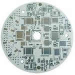
This reference design is for a high-voltage, boost current source for very long strings of LEDs. Applications include LCD TV backlighting, LCD monitor backlighting, streetlights, and parking garage lights. Long LED strings can be a very cost-effective way to drive LEDs. Also, since the LEDs will have exactly the same current, brightness variations are nicely controlled. This design has a 24V input, up to an 80V LED output, and drives 350mA through the LED string. The measured input power is 29.3W and the output power is 26.4W for about 90% efficiency.
PCB
The printed circuit board (PCB) is a general-purpose board for MAX16834 boost designs (Figures 1 and 3). Therefore, there are many components that are either shorted or not populated. These components are indicated on the schematic (Figure 2). Figure 4 shows a bill of materials for this design.
Topology
This design is for a 300kHz discontinuous-boost regulator. In Figure 5, the spreadsheet printout shows the calculated RMS and peak currents in the MOSFET and inductor. Discontinuous designs do, admittedly, have some disadvantages, notably higher MOSFET and inductor currents. However, since the output current is essentially zero when the MOSFET (Q1) turns on, the reverse recovery losses in the output diode (D2) are minimal. This advantage outweighs the design disadvantages, because overheating and noise caused by reverse-recovery currents are difficult to manage. Inspecting the circuit waveforms in Figure 6, you see that the on-time of the MOSFET is about 1.6µs. Once the MOSFET turns off, the drain voltage jumps to 75V for about 1µs, while the inductor conducts to the output capacitors. After that, the inductor energy is essentially drained, and for another microsecond the inductance and MOSFET output capacitance ring until the next on-time.
MOSFET Drive
Because of the discontinuous design, the peak MOSFET currents are more than twice what they would be with a continuous design. However, since there is no current through the MOSFET during turn-on, it only experiences switching losses during turn-off. The MAX16834 drives the MOSFET hard enough for the switch to turn off in about 20ns (Figure 7), thereby keeping the temperature rise low. If EMI becomes a problem, the series resistance and diode on the MOSFET gate can be altered to adjust the switching times. If needed, place a second MOSFET, Q2, parallel to Q1 to reduce the temperature rise.
Output Capacitance
$2.00
Buy It Now
27 watching | 55 sold
The DSP10 is a multi-purpose 10-LED bargraph display PCB for use as a stand-alone bargraph display or with Onstate bargraph meter modules (BM-series). It is designed for use with 3mm, 5mm, 5050 SMD or...
100Pcs 3mm Round LED Bright Light Bulb for PCB board
$0.99
Buy It Now
Free Shipping
20 watching | 221 sold
100pcs 3mm LED Light. The 100pcs item are one color. Because the color of each arrival is not the same. For PCB board.
4pcs 1.4"x3" DIY 12V DC 24 LED 5050 PLCC-6 Light PCB circuit board blank
$9.99
Buy It Now
29 watching | 69 sold
This is for 4 pieces of 1.4" x 3.0" lead free printed circuit board blanks (PCB) designed and manufactured in the USA. The back side is flat & blank exposed tinned copper and not connected to the elec...
For the input and output capacitance, the driver uses long-life electrolytic capacitors. Electrolytic capacitors are neither as durable nor as small as ceramic capacitors, but they have the advantage of providing plenty of capacitance at an economical price. To maintain a low profile (10mm), the capacitors lie in a horizontal orientation. The input and output capacitors are rated for 4000 hours and 8000 hours, respectively, at a temperature of +105°C. As a general rule, electrolytic capacitors double their lifetimes for every 10°C reduction of ambient temperature. This means that for an ambient of +65°C, you can expect the input/output capacitors to maintain performance for 64kHrs/128kHrs. In Figure 5 the spreadsheet printout indicates that, to achieve the desired output-ripple voltage, you need only about 6µF of output capacitance. Because electrolytic capacitors have a limited ripple-current capability, this design uses two 47µF capacitors. The large amount of capacitance eliminates most of the switching-frequency ripple voltage (Figure 8). However since the capacitance is electrolytic with significant equivalent series inductance (ESL), the circuit noise created when the switching MOSFET turns off is not fully filtered. Adding ceramic capacitance or a low-Q LC filter on the output reduces this problem. Since each of these options has some cost, it is best to determine whether there is a problem with the high-frequency spike before trying to fix it.
Summary
So there you have it, now you should know why you need an LED heat sink. When choosing your heat sink and finding which heat sink to use, remember to take into account all the factors that contribute to heat and the cooling process:
LED wattage
The number of LEDs you are powering
The temperature of the environment where the LEDs will be running
Whether the LEDs are mounted in an enclosed or open space.
Stay tuned for more posts on LED heat sinks and choosing the right one, but this should get you started in setting up your LED system!
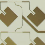
FIG. 1. Packaged LEDs come in a variety of package types including the chip-scale package (CSP) devices pictured from Samsung (top left), the mid-power LED from Lumileds (top right), and the chip-on-board (COB) LED from Cree (bottom).
Packaging options
There are broadly two approaches to HB LED packaging. Manufacturers can either package a single large LED die, or cluster of die (e.g., one red, one green, and one blue), into a device that can be assembled using surface-mount technology (SMT). Or manufacturers package a number of die directly onto what is essentially a printed-circuit board (PCB) - the chip-on-board (COB) approach. Fig. 1 includes samples of different package types from manufacturers Cree, Lumileds, and Samsung.
On the face of it, COB LEDs are a no-brainer. By mounting the bare LED die directly onto a PCB, rather than packaging the die prior to surface mounting them onto a PCB downstream, a whole process step is removed. This clearly makes COB devices a more cost-effective option.
The downside to COB LEDs is that they tend to be wide-angle emitters. These are used in luminaires such as high-bay and street lights. But where a directional light beam is required - for instance, in automotive headlights or ceiling downlights - surface-mountable HB LEDs rule.
HB LEDs and the benefits of ceramics
A key requirement for directional HB LED packaging is that both sides of the packaging substrate need to be "circuitized," with copper tracks through the substrate providing connection between the two sets of circuits. This need is critical as the packaging substrate will be mounted onto a module or luminaire circuit that needs to provide the power to the LED die. Through-holes filled with conducting copper are required but these through-holes need to be isolated from the rest of the circuit. This fact discounts materials that cannot easily have electrically isolated through-holes such as metal-core PCBs (MCPCBs).
Up until now, the only mass-market material that could meet this requirement was electronics-grade ceramic. Ceramic is ideal as it is a natural dielectric - a through-hole drilled into the substrate will be electrically isolated from the rest of the material - and certain types of ceramic are acceptably good thermal conductors.
There is another reason why ceramics are such a good choice: They are able to go through very high resolution direct-plated copper (DPC) circuitization processes. DPC is an additive process where the copper tracks are sputtered onto the ceramic to build up the circuit, as opposed to using a reductive process where the copper is removed from between the tracks using chemicals. This process builds copper up extremely accurately, to precision measured in microns, providing the fine detail required for HB LEDs.
This is where the low-cost MCPCB option again falls flat. To make the dielectric layer for an MCPCB, epoxy is added to glue the copper circuit to the surface of the metal core. It's this epoxy layer, usually mixed with grains of ceramic to improve the thermal performance, that acts as the dielectric. This can only go through a reductive process, which simply doesn't offer a high enough resolution. Again, ceramics are the only option.
Power Supplier: Switch power supplier, DC/DC Converters, SW Regulator and so on
Communication equipments: High-frequency increaser; Filter Circuit and Transmitter Circuit
Office automation Equipment: Motor Driver and so on.
Motor Car: Electronics Regulator; Ignition; Power controller and so on.
Computer: CPU Board, Floppy disk Driver, Power supplier and so on.
Power Modules: Current Converter, Solid relays; Power rectifier bridges.
LED Lighting: High-power LED Lights, LED Curtain Wall and So on.
Metal Substrate Layer: 0.8mm; 1.0mm; 1.5mm; 2.0mm; 3.0mm
Copper foil: 1oz; 2oz; 3oz
To understand how SinkPADTM technology works let's first review the primary thermal path found in LED applications. In a LED the heat originates at the chip (die) in the same way that in a normal light bulb heat originates at the filament. The key difference is that in the case of a light bulb the heat is radiated into the atmosphere and in the case of a LED heat must be conducted through a series of mediums before it reaches the atmosphere. A high rate of thermal conduction means cooler running LEDs while a low rate means very hot and potentially self-destructive LEDs. If all substances had the same and low thermal resistance then it would not matter how many mediums heat would have to be conducted through before it reached the atmosphere. Since this is not the case, an ideal situation is one in which any substance with a low thermal conductivity & a high thermal resistance is removed from the conduction thermal path. These low thermal conduction/high thermal resistance substances slow the transfer of heat and therefore increase junction temperature. Typically conventional MCPCBs are commonly used to dissipate heat from a LED to a heatsink. MCPCB uses a thermally conductive dielectric layer to bond circuit layer with base metal (Aluminum or Copper). The key to thermal performance of MCPCB lies in its dielectric layer. Even though thermally conductive dielectric has higher thermal performance copared to standard dielectric material it is still a weakest link in the conduction thermal path in the MCPCB. SinkPADTM PCB approach overcomes this limitation and eliminates use of a dielectric material completely from a conduction thermal path. SinkPADTM Technology provides “Direct Thermal Path”, lowering LED junction temperature.
Most printed circuit boards are manufactured using glass-reinforced epoxy laminate as the substrate. While there are a wide variety of laminates available on the market, FR-4 is both versatile and well-accepted as a standard material for PCB manufacture. FR-4 functions well as an electrical insulator, and has a good strength-to-weight ratio, and is flame resistant.
The standard FR-4 material that is used in our products is a high temperature, high Td, low CTE 150Tg material.
If a higher Tg material is required, we do stock a 170Tg version of our standard FR-4 material as well, that can be selected in the quoting process.
Note: The 170Tg FR-4 material has equivalency for electrical and mechanical properties with the popular Isola 370HR material, and functions very similarly. There is one documented physical difference, Isola's 370HR is listed as a 180Tg material.
Glossary:
Dielectric Materials
A dielectric material is a substance that is a poor conductor of electricity, and used as an insulating layer in the PCB build up. Porcelain, mica, glass, plastics and some metal oxides are good dielectrics. The lower the dielectric loss, (the proportion of energy lost as heat) the more effective the dielectric material. If the voltage across a dielectric material becomes too great -- that is, if the electrostatic field becomes too intense -- the material will suddenly begin to conduct current. This phenomenon is called dielectric breakdown.
Pre-impregnated (Pre-preg)
Contraction of "pre-impregnated composite fibers", and in the manufacture of PCBs, pre-pregs help influence the performance characteristics of the printed circuit board.
A term also used in the PCB fabrication industry to describe the bonding ply materials used to bond the layers of a multilayer PCB together.
Other applications for aluminum PCBs include power supplies, high-current circuitry, motor controllers and automotive applications. Aluminum core PCB materials are very effective in thermal heat dissipation applications that involve high-power surface mount integrated circuits. Because of the high level of thermal dissipation associated with aluminum-backed PCBs, circuit board designs can be simplified. Aluminum PCBs eliminate forced air and heat sinking, which ultimately lowers the design cost. Just about any design than can be made better by improving thermal conduction and temperature control is a candidate for an aluminum-backed PCB.
While traditional PCBs use a fiberglass substrate (FR4 is standard), aluminum base PCBs consist of an aluminum backing, thermally conductive dielectric layers and standard circuit layers (a thin PCB bonded to the aluminum backing). As a result, the circuit layers can be just as complex as the layers mounted on traditional fiber PCBs.
Aluminum-backed PCBs can reliably increase durability and shelf life of a design through temperature control and associated reductions in failure rates. Aluminum designs also deliver better mechanical stability and low thermal expansion levels than other PBS designs.
For furhter information, please feel free to contact us, www.pcbsino.com