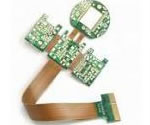
Flex PCB stiffener Flex PCB application
China Flex PCB Manufacturing, Shenzhen Flex PCB Manufacturer, Making Flex Circuit boards
Flex PCB Contract manufacturer, PCB Fabrication, Turnkey assembly services
Buy Flexible Print circuit board, customer: /USA/UK/Canada/South Africa...
Flex PCB Supplier Shenzhen, China, Flex PCB Manufacturer, Turnkey services
-
PCBSINO is the Top 5 PCB manufacturer company in China.
PCBSINO do rapid Flexible PCB Prototype within. we can make Flexible Print circuit boards and Rigid circuit boards, Flex and Rigid Flex PCB, single side, double side, multilayer Flexible print circuit board
PCBSINO making many type electronic product for our customer, Our turkey services team can source original components part for your project(Digikey/Mouser/RS...), senior Electronic engineer will follow each step of the production to solve any PCB problem and our team will do final function test in PCB house.
Flex PCB |
|
Rigid FlexPCB Rapid Prototype |
| Flex PCB |
|
prototype of Flex PCB |
| Flex Prototype |
|
Rigid-Flex PCB Rapid Prototype China, |
Turnkey Services |
|
Turnkey Flex PCB Assembly Services, |
| PCB assembly |
|
Print circuit board Manufacturing, Turnkey assembly |
| PCBA Assembly |
|
SMT Assembly, EMS/OEM supplier China |
Flex PCB stiffener Flex PCB application
-
Flex PCB stiffener Flex PCB application
Stiffeners are materials added to a flex circuit to rigidize particular areas. Rigidizing is recommended under smt components, for example, but not required. Other areas to consider rigidizing include:
Component / Connector Stiffeners
Function:
Creates a localized rigid area where components / connectors are attached.
Protects solder joints by preventing bending of the flex in component area.
Material Options:
Polyimide stiffeners are the most common method to achieve the thickness requirement, at the contact fingers, as specified by the ZIF connector that the flex circuit plugs into. Some common thickness requirements are 0.3mm or 0.2mm. This thickness is be achieved by adding a thin Polyimide layer in the finger area only per the connector specifications. Stiffener thickness can vary between 0.002” and 0.008” depending upon the flex circuit material construction what the added amount is required to meet the connector spec.
It is not recommended to design a “thicker” flex PCB in an attempt to eliminate the need for a ZIF stiffener. This will result in an excessively thick part that will not have the required flexibility or bend reliability and will be much more costly. ZIF connectors have tight dimensional tolerance in the finger area width, so only a thermally bonded Polyimide stiffener can be used for this application.
Stiffeners for ZIF connectors can be attached to one or both sides of a flex circuit design. It is recommended to include the ZIF connector part number in the part data/drawing to allow your supplier to review and ensure the flex design meets the appropriate connector specs.
There are many benefits to Flexible Printed Circuits including:
Assembly Error Reduction – With accurate designs and automated production, flex circuits eliminate human errors once involved in hand-built wire harnesses. With the exception of production-induced errors, circuits are ONLY routed to those points called for by the accurate design plan.
High Density Applications – Flexible circuits allow for minutely narrow lines giving way to high density device population. Denser device populations and lighter conductors can be designed into a product, freeing space for additional product features.
Improved Airflow – Because of their streamlined design, flex circuits allow for the flow of cooling air through an electronic application.
Increased Heat Dissipation – Due to the larger surface-to-volume ratio and compact design of flexible circuits, a shorter thermal path is allowed. Further, the thinner design of flex circuits allows for heat dissipation from both sides of the circuit.
Increased System Reliability – In the past, most circuit failures occurred at an interconnection point. Flex circuits can be designed so that interconnections are reduced, which in turn, increases the reliability of a circuit.
The PCB cross-section editor for a single stack-up must now support multiple cross-sections representing the different PCB laminates. In addition to supporting conductor, plane and dielectric layers, cross-section editors need to include new mask and coating layers above and below the surfaces of the flex PCB, such as:
Electroless nickel electroless palladium immersion gold (ENEPIG) for special plating areas.
Stiffeners – aluminum or stainless steel – that restrict flexing where components are mounted, to avoid cracking or peeling.
Material masks that include (precious) metals, adhesives and solder paste masks.
A coverlay (cover layer), which is an adhesive-coated film pressed onto the stack-up to insulate the circuit.
Advances in fabrication have extended to materials and the number of additional mask/conductive layers for flex and rigid-flex PCBs. New materials – conductive/nonconductive layers, and surface finishes – require designers to manually check if the design elements on the flex circuit are meeting the fabricator’s design guidelines. This adds a substantial amount of time to the design stage.
Elcom insists in providing high-quality and high-reliability flexible PCB to our clients. All flexible PCB products pass strict quality control processes. The customized flexible PCB/PCBA are available with our well-established and efficient OEM/ODM procedure. If you are interested in our flexible PCB products, please feel free to contact our service-oriented project managers!
ifferentiating from FR-4 PCB stiffener fixed method, Polyimide and polyester stiffeners are fastened using an adhesive, or a heat set adhesive.
That is the reason why some of polyamide stiffener has been shedding risk.
Of course, usually experience flex PCB manufacturers can produce high quality Polyimide stiffener on the board.
Bonded with PSA or thermal-set adhesive
Used to add thickness, or add strength in high wear areas
THERMOSETTING ADHESIVE FILMS
Thermosetting glue bonding movies, such as cast acrylic films or flex circuits bond plies, can also be used to bond flex circuits to stiffeners, but call for the moment and expense of an extra lamination step. Even so, thermosetting film adhesives could offer high bond toughness of the flex to the support.
I'm struggling to find some guidelines for the thickness to specify for a polyimide stiffener under a surface mount connector on a flex board. I see lots of call us and we'll help you figure it out but no guidelines or explanations. I want to use one under a small 20 pin surface mount connector both to keep things flat for assembly and to provide some relief for multiple removal/insertion cycles (100 or less).
LIQUID ADHESIVES
Oneand two-part fluid epoxy kind adhesives have been utilized for bonding stiffeners to flex circuits. They are challenging to use uniformly and also consequently do not appreciate broad popularity. Liquid adhesive materials are well-suited as well as can be wellapplied to develop pressure alleviation at the transition edge of the flex PCB and support by producing a bead of epoxy along the whole side of the change.
THERMOPLASTIC ADHESIVE FILMS
The use of thermoplastic-based adhesive movies for bonding flex PCB to stiffeners is one more common alternative. Thermoplastic films have some distinct advantages amongst adhesives since they are low-stress, fully-polymerized polymer resins that require no treatment. Characteristic including bond to a wide range of surfaces and products as well as the reported capability to be reworked easily might cause a development of sticky products make use of in the future
Why flexible PCBs are getting popular?
The technology offers reduced volume and weight, increased electrical performance, larger design freedom and improved interconnect reliability. Increased use in handheld and mobile devices demand reduction in form factor, increased functional density and enlarged user comfort, which can only be achieved with flexible printed circuit board technology. Flexible circuit board is generally installed bent, folded or twisted. Flexible PCBs have not only replaced wiring and connectors but allowed designers to create configurations and complex geometries that were impracticable with rigid printed circuit boards.
Basics of Flexible Circuits
Two major varieties of flexible circuits can be manufactured
(1) Pure Flexible PCB
(2) Rigid-flexible PCB
Pure Flexible PCB
Flexible Printed Circuits Boards made their introduction into the electronics industry as substitutes for cable assemblies. It is a patterned arrangement of printed circuitry and components that utilizes flexible based material with or without flexible coverlay. Flexible PCB is nothing but a pattern of conductive traces bonded on a flexible substrate like polyimide (PI) – similar to FR-4 and CEM in rigid PCBs.
The thickness of Polyimide flex PCB stiffener material.
Polyimide film is used when the additional thickness required is 0.002″- 0.009″. Polyimide stiffeners can have coincidental edges of the circuit outline.
Third flex PCB stifferner material: Other materials
This part content is very special for most egineers.
Because most of we have saw above two type flex PCB stiffener material.
Only in some special conditional, flex PCB manufacturers can consider other special PCB stiffener.
By the way, usually small flex PCB manufacturers can just use FR-4 or Polyimide flex PCB material.
Even some Other materials such as Stainless steel, Aluminum, Ceramic or molded plastic components can also be used as stiffeners for specific design requirements.
Standard flex circuit adhesives or pressure sensitive adhesives can be used to provide varying performance alternatives.
Inquiry
Single Sided Flexible PCB
Single layer Flexible PCB consisted of one conductive layer, suitable when space is limited.
To avoid manual checks and ensure the design is created correctly, designers need in-design inter-layer checks to flag issues as they are created. Checking at the manufacturing sign-off stage is too late in the design cycle to find errors, and makes the design process unpredictable. Real-time capability can avoid time-consuming steps later in the process.
In-design inter-layer checks can reduce errors that may be introduced during the design process, including the following areas:
Gap/overlap between mask layers.
(Precious) metal-to-coverlay, mask-to-pad, coverlay-to-pad.
Bend area/line to stiffener, component, pin and via.
Edge-to-edge gap in areas such as the bend line to the component, via-to-bend line, and stiffener-to-bend area.
Minimum overlap, such as when two geometries overlay by a minimum or more (e.g., solder mask overlay into the transition zone).
Gold mask-to-coverlay, stiffener adhesive-to-stiffener, and pin-to-coverlay.
Point-to-Point Wire Replacement – Depending on the number of point-to-point connections in a circuit design, at Flexible Circuit, we guarantee that we can design and build a single flex circuit that can eliminate many (if not all) of those interconnections. At Flexible Circuit, “We Go Where Others Will Not.”
Reliability and Durability – A flexible circuit can move and flex up to 500 million times without a failure, in designs that have moving parts. The exceptional thermal stability of polyimide also allows the circuit to withstand applications with extreme heat. The thermal stability of polyimide provides a better base for surface mounting than hard boards. Because the compliant base film places less stress on soldered joints, a thermal mismatch is less likely to occur.
Repeatable Routings – Our circuits are made from precise replicas of artwork for superior manufacturing consistency. The etched circuits replace the solder and hand wiring connections of the rigid board, completely eliminating wiring errors.
Simplified Circuit Geometry – Flexible Circuit Technologies places surface mount electronics directly onto the circuit which results in streamlining the overall design. Intricate patterns that were nearly impossible to achieve with rigid boards are made easily in flex circuits.
Decreased Assembly Time and Costs – Flex circuits require less manual labor during assembly and reduce production errors. Flex circuits have an intrinsic ability to integrate form, fit and function. Flex circuits eliminate the high cost of routing, wrapping and soldering wires. Complete interconnection systems are installed or replaced, rather than individual hard PC boards. As a result, wiring errors are eliminated and hence manufacturing costs are reduced. Whether it is a low volume production with a complex circuit or high volume production with a simple circuit, assembly time and costs are decreased.
Design Freedom – Unlike rigid boards, flex circuits are not restricted to two dimensions. Because they are as flexible as wires or ribbon cables, flex circuit design options are endless. At Flexible Circuit, we pride ourselves on taking on the most complex of design challenges. Flex circuits can be designed to meet highly complex and unimaginable configurations while being able to operate in the most hostile environments. Flex circuit designs could entail any of the following:
Highly complex configurations
Withstand hostile operating environments
Single- Double- combinations
Complex interconnections
Shielding
Rigid/flex capabilities
Surface mounted devices
1. Stiffeners are an inexpensive option for rigidizing pin areas, surface mount areas, or hole patterns for component mounting.
2. Stiffeners can be utilized to force a bend line in selected areas.
3. Stiffeners reinforce solder joints and increase abrasion resistance.
4. Circuits may be attached to a stiffener pallet (multiple parts) to provide easier handling for automated pick-and-place and component soldering. Circuits can be held together for processing on the pallet, then singulated (clipped free) after wave soldering and circuit testing.
5. Stiffeners can be marked with component mounting locations for rapid assembly.
6. When using multiple stiffeners, maintaining the same stiffener thickness consistent throughout the entire construction can help lower costs.
7. Stiffeners can also be used to perform specific functions such as heat dissipation and strain relief.
Processes involved in rigid-flex and flex Printed Circuit Board (PCB) manufacturing do not allow manufacturing them in all shapes and configurations. Additionally, manufacturing large PCBs generally affects the manufacturing tolerances and dimensional stability. That makes it important to consider the shape and size of the flex part of the PCB.
Manufacturers add value by improving the reliability of flexible PCBs through use of stiffeners that support soldered components and connectors. Although not all rigid-flex and flex PCB need stiffeners on both sides, laminations on the top and bottom of the PCB are essential when components are to be assembled on both sides. Additionally, some designs may need epoxy strain relief if a bend is situated close to the rigid PCB section or the stiffener.
Functions of the Stiffener
PCB stiffeners reinforce the areas where components will be assembled, and provide high reliability during the component assembly process. Although the flexing area of the flex and rigid-flex PCB does not need a stiffener in general, an overlap of the overlay termination points and the stiffener is essential to avoid stress points.
Materials Used As Stiffeners
Manufacturers use different materials as stiffeners. Primarily, there are three types of materials—FR4/G10, Polyimide, and others. FR4/G10 stiffeners are usually bonded with PSA or thermal-set adhesives to add rigidity to the connector areas or to be used as carrier panel. Likewise, Polyimide stiffeners are also bonded with PSA or thermal-set adhesives, but they add to the thickness, or add to the strength in areas facing high wear. Other materials such as stainless steel, Aluminum, and ceramic are also frequently used as stiffeners. Manufacturers often use Kapton when the end of a flex PCB needs to be thickened for insertion into a ZIF socket. However, this requires a separate lamination cycle.
Placement of Stiffeners
Placement of stiffeners depends on the nature of the material used and the required thickness. However, for avoiding stress, overlapping of the stiffener and the overlay termination points is necessary to avoid stress. When arrays are to be routed and retained, manufacturers extend the same stiffening material into the array to make it more rigid
Stiffeners can be used to reinforce the areas where components will be assembled, but not where the board will flex. If your board requires stiffeners on both sides of the flex, it may require two laminations. Also keep in mind that stiffeners require their own prepreg lamination cycle, and certain stiffener materials require an additional lamination cycle as well. They add thickness to your board, and impact both cost and manufacturing time. However, there are certain cases where stiffeners are required.
Flex-only PCBs can withstand fewer components than rigid-flex. The rigid part of rigid-flex can also be as complex as a traditional rigid PCB. Stiffeners are occasionally laminated the same time as the coverlay.
Stiffener Materials
Stiffeners are typically made of FR-4 or Kapton. Kapton is often used when the end of the flex must be thickened and inserted into a ZIF connector. However, the use of Kapton requires a separate lamination cycle. FR-4 stiffeners can be done within the same lamination cycle.
Route And Retain With Stiffeners For Flex PCBs
When routing and retaining arrays, the same material as the stiffener will simply be extended into the array. This rigidizes the array.
Adding Stiffeners for Bend Constraints
Stiffeners are also be used to restrict the bend areas to specific location(s) within a flex design to either facilitate the final assembly process or to achieve a specific bend requirement or end use function.
These stiffeners are typically an added thin layer of Polyimide material, usually 0.002” – 0.008”, but thicker layers of FR4 can be used if required.
A design review should always be done to ensure that the stiffener(s) do not create any mechanical bend stress concentrator that may result in a kink in the part rather than a bend in a preferred smooth arc.
Summary
The purpose of a flex circuit stiffener is to add a significant amount of functionality to your design and can be configured in an extremely wide range of combinations. All stiffener types can be combined in any flex PCB design. The mechanical nature of a stiffener’s function is one area of flex design that differs significantly from that of rigid printed circuit boards. This is a significant area in which our customers require design support to ensure that the finished parts meet their requirements.
FR4, Polyimide, Aluminum, Stainless Steel
Variety of thicknesses available
Attachment methods:
Thermally bonded with flex adhesive
Pressure Sensitive Adhesive (PSA)
Hole patterns
Forcing bends
Increasing overall thickness
Protecting solder joints
Die attach platform for wire bond components
Heat dissipation
TYPES OF STIFFENER MATERIALS
For furhter information, please feel free to contact us, www.pcbsino.com