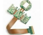
mobile Flex PCB multilayer design Flex PCB application
China Flex PCB Manufacturing, Shenzhen Flex PCB Manufacturer, Making Flex Circuit boards
Flex PCB Contract manufacturer, PCB Fabrication, Turnkey assembly services
Buy Flexible Print circuit board, customer: /USA/UK/Canada/South Africa...
Flex PCB Supplier Shenzhen, China, Flex PCB Manufacturer, Turnkey services
-
PCBSINO is the Top 5 PCB manufacturer company in China.
PCBSINO do rapid Flexible PCB Prototype within. we can make Flexible Print circuit boards and Rigid circuit boards, Flex and Rigid Flex PCB, single side, double side, multilayer Flexible print circuit board
PCBSINO making many type electronic product for our customer, Our turkey services team can source original components part for your project(Digikey/Mouser/RS...), senior Electronic engineer will follow each step of the production to solve any PCB problem and our team will do final function test in PCB house.
Flex PCB |
|
Rigid FlexPCB Rapid Prototype |
| Flex PCB |
|
prototype of Flex PCB |
| Flex Prototype |
|
Rigid-Flex PCB Rapid Prototype China, |
Turnkey Services |
|
Turnkey Flex PCB Assembly Services, |
| PCB assembly |
|
Print circuit board Manufacturing, Turnkey assembly |
| PCBA Assembly |
|
SMT Assembly, EMS/OEM supplier China |
mobile Flex PCB multilayer design Flex PCB application
-
mobile Flex PCB multilayer design Flex PCB application
Assembly Error Reduction – With accurate designs and automated production, flex circuits eliminate human errors once involved in hand-built wire harnesses. With the exception of production-induced errors, circuits are ONLY routed to those points called for by the accurate design plan.
Decreased Assembly Time and Costs – Flex circuits require less manual labor during assembly and reduce production errors. Flex circuits have an intrinsic ability to integrate form, fit and function. Flex circuits eliminate the high cost of routing, wrapping and soldering wires. Complete interconnection systems are installed or replaced, rather than individual hard PC boards. As a result, wiring errors are eliminated and hence manufacturing costs are reduced. Whether it is a low volume production with a complex circuit or high volume production with a simple circuit, assembly time and costs are decreased.
Design Freedom – Unlike rigid boards, flex circuits are not restricted to two dimensions. Because they are as flexible as wires or ribbon cables, flex circuit design options are endless. At Flexible Circuit, we pride ourselves on taking on the most complex of design challenges. Flex circuits can be designed to meet highly complex and unimaginable configurations while being able to operate in the most hostile environments. Flex circuit designs could entail any of the following:
Highly complex configurations
Withstand hostile operating environments
Single- Double- combinations
Complex interconnections
Shielding
Rigid/flex capabilities
Surface mounted devices
As devices get more compact, there is less room to accommodate a material’s expansion or contraction as internal temperature fluctuates. PCB manufacturer Elmatica (Oslo, Norway) lists the coefficient of thermal expansion (CTE) for a typical FR-4 as 14 to 17 ppm/°C. Yet components attached to the PCB can have an expansion rate as low as 6 ppm/°C. This difference is enough to shear solder joints when the PCB heats up.
Another issue for composites, says Tarun Amla, executive VP/CTO for PCB laminate source Isola Group, is that “glass/epoxy composites exhibit anisotropy, both in dielectric constants and dissipation factors. For example, CTE in the x and y directions may range from 12 to 25 x 10-6 m/m, but is closer to 40 to 90 x 10-6 m/m in the z-direction.” He suggests that demand for isotropic substrates might reduce the use of glass/epoxy in PCBs.
Elmatica maintains that using metal cores — e.g., copper-Invar-copper (CIC) and copper-molybdenum-copper (CMC) — is expensive and presents machining issues, as do laminates made with aramid fibers. Elmatica, therefore, favors STABLCOR, a thermally and electrically conductive laminate available in carbon fiber/epoxy or carbon fiber/polyimide. Developed by NASA, the material is supplied to licensed manufacturers only by STABLCOR Technology Inc.(Huntington Beach, Calif.). The company explains that STABLCOR does not replace all FR-4 laminates in a multilayer PCB, but instead is used selectively to reduce CTE mismatch and improve thermal management. Integration of STABLCOR at the right location in the PCB stack reportedly makes a CTE of 8 to 10 ppm/°C possible and increases rigidity without adding weight. Many other materials are being explored to help produce lower CTE laminates, including liquid crystal polymers and ceramic matrix composites (CMCs).
Wire harness conversion to flex reduces wiring errors from hand made connections and decreases assembly time
Flexibility during Installation – Flexible Circuits allow a third dimension to work with because they can interconnect between two or more planes during execution. As a result, they solve space and weight problems unmatched by rigid boards. Flex circuits can be manipulated many times during installation and execution without electronic failure.
Benefits of using Flex PCBs
The mechanical and electrical needs of a project determine the type of flexible circuit used.
When selecting a flex, weigh the advantages of the circuit against the total installed cost, including inspection, interconnection, tooling and testing. PFC can help you make an informed decision.
The use of flex circuits has been a key player in the modern technology era. In general, flexible circuits provide a solution to a variety of electronic design constraints. As the name implies, flex circuits are implemented to help PCB engineers solve issues within the PCB design industry, whether it is an issue of flexibility, tightly packed boards where electronic connects are required in 3 axes (static application), applications where light weight is a priority or situations when space, cost, and performance are a concern.
Flexible circuits provide designers with more freedom to create a design to fit a particular device rather than a device to fit the circuit board design. When talking about flex circuits it is important to note that there are several different types including single-sided, double-sided, multi-layered, and rigid-flex, all serving a slightly different purpose for the PCB design and implementation. Knowing the differences between these categories of flexible circuits will help you determine the most efficient way to design you latest project.
High-frequency PCB materials often include FR4-grade glass-reinforced epoxy laminate, polyphenylene oxide (PPO) resin and Teflon. Teflon is one of the most expensive options available because of its small and stable dielectric constant, small amounts of dielectric loss and overall low water absorption.
Many aspects need to be considered when choosing high-frequency PCB board and its corresponding type of PCB connector, including:
• dielectric constant (DK)
• dissipation
• loss
• dielectric thickness
The most important of those is the Dk of the material in question. Materials with high probability for the change of dielectric constant often have changes in impedance, which can disrupt the harmonics that make up a digital signal and cause an overall loss of digital signal integrity — one of the things that high-frequency PCBs are designed to prevent.
Rigid-Flex circuitry provides a simple means to integrate multiple PCB assemblies and other elements such as display, input or storage devices without wires, cables or connectors, replacing them with thin, light composites that integrate wiring in ultra-thin, flexible ribbons between sections. In rigid-flex packaging, a flexible circuit substrate provides a backbone of wiring with rigid multilayer circuit sections built up as modules where needed.
Flex and Rigid-Flex applications also provide increased reliability. Mean time between failure rates (MTBF) typically exceed those of standard PCB sets with discrete wires and connectors, often becoming the choice of companies and engineers alike for its dependable and consistent performance.
TTM has extensive experience, product knowledge and technical competency in this area. Our products can be found in the satellites, multiple military aircraft types and missile platforms. Joint development work is also done routinely with NASA and related agencies, as well as many others in the space and aerospace community. TTM's Flex & Rigid-Flex expertise can also be found in various medical and health related test equipment, computing networks, and various scientific and industrial applications.
Rigid-Flex product types include:
Flexible Circuits
Rigid-flex PCBs
Rigid-flex circuitry provides a simple means to integrate multiple PCB assemblies and other elements such as display, input or storage devices without wires, cables or connectors, replacing them with thin, light composites that integrate wiring in ultra-thin, flexible ribbons between rigid sections. In rigid-flex packaging, a flexible circuit substrate provides a backbone of wiring with rigid multilayer circuit sections built up as modules where needed.
Since the ribbons can be bent or folded, rigid-flex provides a means to compactly package electronics in three dimensions with dynamic or static bending functions as required, enabling miniaturization and thinness of product design. The simplicity of rigid-flex integration also generally reduces the number of parts and interconnections required, which can improve reliability. The increasing popularity of mobile electronics coupled with the design trend of developing increasingly thinner, lighter and more feature-rich products, is expected to further drive growth in the rigid-flex and flex sectors, where these PCBs are the backbone of miniaturization.
Rigid-flex technology is essential to a broad range of applications including aerospace and defense, industrial and transportation systems requiring high reliability; hand-held and wearable electronics such as mobile phones, video cameras and music players where thinness and mechanical articulation are essential; and ultra-miniaturized products such as headsets, medical implants and semiconductor packaging where size and reliability are paramount.
Flex and rigid-flex PCBs have a wide range of applications - from military weaponry and aerospace systems to mobile phones and digital cameras. Their use in medical equipment is constantly increasing due to their improved reliability.
Flexible circuits have the advantages of fitting in any geometrical shape while retaining the precision density and repeatability of printed circuits.
Download this guide book, aimed at designers of all levels and abilities, to broaden your understanding of how flex and rigid-flex boards are actually made, the design issues imposed by the materials used and the best practices for flex and rigid-flex PCB design.
These are flexible circuit boards used for high-precision information equipment. These products are indispensable when a flexible wire connection is required.
Flexible circuits (FPC) are flexible circuit boards. They are widely used for digital equipment such as personal computers, cameras, and mobile terminals, which are undergoing continuous miniaturization.
The use of thin, light, and flexible circuits increases design flexibility in response to the diversified designs and complex forms of electronic equipment. In addition, we have succeeded in high-density packaging by taking advantage of their flexibility and by integrating micropatterned boards into the flexible circuit.
Type 1: Single sided flexible material with or without shield(s) or stiffener (one conductive layer).
Type 2: Double sided flexible material with or without shield(s) or stiffener (two conductor layers) with plated through holes.
Type 3: Multilayer flexible material with or without shield(s) or stiffener (more than two conductor layers) with plated through holes and HDI.
Type 4: Multilayer rigid and flexible material combinations (more than two conductor layers) with plated through holes and HDI.
Other things to consider when choosing the boards and PC connector types to use when designing a high-frequency PCB are:
• Dielectric loss (DF), which affects the quality of signal transmission. A smaller amount of dielectric loss could make a small amount of signal wastage.
• Thermal expansion. If the thermal expansion rates of the materials used to build the PCB, such as copper foil, are not the same, then materials could separate from each other due to changes in temperature.
• Water absorption. High amounts of water intake will affect the dielectric constant and dielectric loss of the PCB in question, especially if it is used in wet environments.
• Other resistances. The materials utilized in the construction of a high-frequency PCB should be rated highly for heat resistance, impact endurance and resistance to hazardous chemicals, as necessary.
Aluminum-Backed PCBs
Aluminum-backed PCBs are designed in much the same way as their copper-backed counterparts. However, instead of the usual fiberglass used in most PCB board types, aluminum-backed PCBs make use of aluminum or copper substrate board.
Market Trends in Flex PCB
According to the Global Industry Analysts Inc., the projection for Flex PCBs in the global market is pointing towards US$15.2 billion by 2020. Several factors are contributing to this trend. Chief among these are the emergence of wearable electronics, polymer plastic solar cells and foldable and rollable smartphones. This has led to an unrelenting focus on the manufacture, performance, and design of special printed circuit boards, mainly of the flexible type. The growth in the market is coming from technological advances in conductive and substrate materials, along with developments in fabrication such as in special copper etching techniques.
Market Areas Driving the Demand
The burgeoning opportunities for flexible electronics are mainly coming from the healthcare sector and are driving the main benefit for growth. With electronic packaging shrinking in size, the need for superior packaging flexibility is driving the interest in flexible PCBs. The growth of disposable electronics is also causing a spurt in the opportunities. Technological advances in flexible ceramics are helping manufacturers shrink the size of substrate materials. The auto end-use sector is helping to drive the demand for flex PCBs as more promising applications are discovered in the areas of haptics and structural electronics.
Technological Trends in Flex PCB Design and Manufacturing
Although from the technological point of view, a conventional multilayer PCB still corners a large share of the market, the global trend of shrinking of electronic products is pushing up the requirements for HDI, Rigid-Flex, and Flex technology. The challenge to the manufacturers comes from designing ultra-thin PCBs that must also meet the requirements of signal integrity and EMC specifications while still being low cost.
The PCB industry often needs to increase the layer count within reducing thicknesses of circuit boards—all without compromising the electrical performance and structural rigidity of the PCB. For instance, they expect to reduce the current PCB thicknesses of 0.5-0.7 mm to lower than 0.4 mm in the future. Similarly, the 0.7 mm pitch of a BGA package has already come down to 0.4 mm, and expected to reach 0.3 mm—offering higher pin counts within reduced PCB real estate.
Following the same pattern, pad/hole sizes of microvia are fast coming down to 150/75 µm. For drilling microvia, the PCB industry currently uses CO2 laser, but they are moving on to new lasers working at picosecond pulses. These will offer still finer holes, and lower the thermal damage drastically. HDI technology is coming up with Any Layer Via (ALV), although this is still expensive, requiring state-of-the-art technology. The next generation of wearable and handheld devices is already demanding a buildup of 10 to 12 layers of microvia.
Single-layer Flex Circuits
A single-layer flex circuit also referred to as a single-sided flex circuit, is currently the most commonly used type of flexible circuit—and the cheapest. Single-layer flex circuits consist of one conductive layer bonded between two insulating layers or uncovered on one side with cover layers applied to improve the lifespan of the product. This type of circuit has a very thin construction and is most effective in applications where constant motion is expected.
SINGLE-LAYER
Single-layer flexible circuits have one layer of metal on a dielectric. This is the lowest cost flex circuit and is the thinnest, most flexible solution.
Flexibility - the most prominent benefit.
The elastic nature of the flex PCB allows placement around edges and folds.
The flexible nature of the flex circuit boards are used in electronic devices that require 3 axes connections.
Very little or no wiring is required that eliminates wire connection failure and increases the reliability of the device.
Space and Weight Savings
Flex PCBs save up to 60% of the weight and space compared to Rigid PCB or wire harness applications.
Bending Cycles
Flex PCB use in 3D designs eliminates connectors, while the number of bending cycles can be as many as 200,000 (with standard material)
Anti-Vibration Benefits
Added flexibility and lighter weights allow the flex circuits to absorb and reduce the impact of the vibration to itself as well as any solder joints in connections.
Use in Harsh Environment
Flex circuits can be built with materials that are suitable to use in harsh operating environments (materials that have the following properties: waterproof, moisture proof, shock proof, high temperature oil, corrosion resistant).
Consistent Thin Inner Layers
Heavy Copper Layers
Heavy copper layers can be used for high-power uses with thin copper layers for flexibility
High Density Applications – Flexible circuits allow for minutely narrow lines giving way to high density device population. Denser device populations and lighter conductors can be designed into a product, freeing space for additional product features.
Improved Airflow – Because of their streamlined design, flex circuits allow for the flow of cooling air through an electronic application.
Increased Heat Dissipation – Due to the larger surface-to-volume ratio and compact design of flexible circuits, a shorter thermal path is allowed. Further, the thinner design of flex circuits allows for heat dissipation from both sides of the circuit.
Increased System Reliability – In the past, most circuit failures occurred at an interconnection point. Flex circuits can be designed so that interconnections are reduced, which in turn, increases the reliability of a circuit.
Point-to-Point Wire Replacement – Depending on the number of point-to-point connections in a circuit design, at Flexible Circuit, we guarantee that we can design and build a single flex circuit that can eliminate many (if not all) of those interconnections. At Flexible Circuit, “We Go Where Others Will Not.”
Reliability and Durability – A flexible circuit can move and flex up to 500 million times without a failure, in designs that have moving parts. The exceptional thermal stability of polyimide also allows the circuit to withstand applications with extreme heat. The thermal stability of polyimide provides a better base for surface mounting than hard boards. Because the compliant base film places less stress on soldered joints, a thermal mismatch is less likely to occur.
For furhter information, please feel free to contact us, www.pcbsino.com