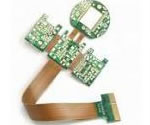
USB2.0 High speed connector Flex PCB application
China Flex PCB Manufacturing, Shenzhen Flex PCB Manufacturer, Making Flex Circuit boards
Flex PCB Contract manufacturer, PCB Fabrication, Turnkey assembly services
Buy Flexible Print circuit board, customer: /USA/UK/Canada/South Africa...
Flex PCB Supplier Shenzhen, China, Flex PCB Manufacturer, Turnkey services
-
PCBSINO is the Top 5 PCB manufacturer company in China.
PCBSINO do rapid Flexible PCB Prototype within. we can make Flexible Print circuit boards and Rigid circuit boards, Flex and Rigid Flex PCB, single side, double side, multilayer Flexible print circuit board
PCBSINO making many type electronic product for our customer, Our turkey services team can source original components part for your project(Digikey/Mouser/RS...), senior Electronic engineer will follow each step of the production to solve any PCB problem and our team will do final function test in PCB house.
Flex PCB |
|
Rigid FlexPCB Rapid Prototype |
| Flex PCB |
|
prototype of Flex PCB |
| Flex Prototype |
|
Rigid-Flex PCB Rapid Prototype China, |
Turnkey Services |
|
Turnkey Flex PCB Assembly Services, |
| PCB assembly |
|
Print circuit board Manufacturing, Turnkey assembly |
| PCBA Assembly |
|
SMT Assembly, EMS/OEM supplier China |
USB2.0 High speed connector Flex PCB application
-
USB2.0 High speed connector Flex PCB application
High-speed cable assemblies with micro coax and twinax cable, for differential and single-ended applications. Assemblies include future-proof, high-density array, integral ground plane, hermaphroditic, rugged Edge Rate® and high-speed PCI Express® systems.
Oki Electric Cable Co., Ltd. (President: Masasuke Kishi, Head Office: Kawasaki-shi, Kanagawa-ken, hereafter referred to as Oki Electric Cable) has recently developed "Long High-Speed Transmission FPC", flexible printed circuits (hereafter referred to as FPC) (*1) with support for long-distance high-speed transmission. This product will commence sales in June 2014.
While information (data) on digital electronic devices continue to get larger and faster in recent years, the demand is growing for more lightweight and compact devices. The thin and lightweight properties of FPC have made them a popular choice for narrow-space wiring in a diverse range of digital electronic devices including smartphones and other portable devices. On the other hand, the base material of FPC presents high conductor resistance during high-speed transmission causing greater pulse attenuation, making FPC unsuitable for long-distance, high-speed transmission compared to cables.
Global Connector Technology's (GCT) Dual USB connector for Raspberry Pi is now available in stock from Newark.
USB1035 Dual USB2.0 type A connector
If you're not familiar with Global Connector Technlogy, here's some background from a PR piece:
GCT delivers 10 million dual USB connectors for Raspberry Pi application
Global Connector Technology (GCT) has shipped its ten millionth Dual USB connector USB1035 for the Raspberry Pi. Two dual USB connectors are used on each Raspberry Pi device to enable the attachment of peripherals such as keyboards, mice and webcams which provide the Pi with additional functionality.
The GCT dual, USB type A, connector was initially chosen for cost, service, lead time and reliability. The challenge as Raspberry Pi sales exploded was to deliver very high volumes to multiple subcontractors handling Pi production.
As sales increased GCT’s production lines were expanded, in order to offer a stable and short lead time. The decision was made to invest in fully automated tooling to maintain a superb level of quality with high throughput. The GCT factory is now capable of producing 1.4 million pieces per month.
“Here at GCT we’ve continued to work closely with Raspberry Pi’s supply chain to not only fulfil orders, but help to plan and ensure increased volumes could be met without any compromise on lead time, price or quality. This ensured that we were able to deliver connectors for the Raspberry PI project as demand grew” stated Andrew Stewart – EU Sales Manager of GCT. “This project shows our flexibility to expand our production capabilities to support our customer’s projects”.
The "Long High-Speed Transmission FPC" recently developed by Oki Electric Cable uses the latest polyimide base material (low dielectric constant and low dielectric tangent material (*2) with transmission loss reduction effect) and features the proprietary transmission line design and long-length construction technique that suppresses the transmission pulse attenuation to enable high-speed transmission. FPC allows maximum transmission distance of 1m at 5Gbps transmission speed, which is equivalent to the USB3.0 standard (*3).
Quick Tip #2 is that Type-C provides myriad ways to power and charge devices—at either end of the cable. Designers need to carefully read the USB-IF specifications referenced above and be careful not to over-design your embedded system. That is: 100W charging isn’t needed for any of the embedded or ultra-mobile devices on the right-hand side of Figure 8.
A fully configured USB 3.0 Type-C system supporting DisplayPort, legacy USB 2.0 as well as GPIO and I2C serial is shown in Figure 8. Not just presented here for discussion purposes, this is a real system that shows the capability of the Type-C connector even if not used with USB 3.1. In fact, because of Type-C’s capabilities—including Power Delivery—many designs may stay with USB 3.0 while incorporating alternate channels as shown.
Of note in Figure 8 are the Type-C PD controller (controlled by I2C or GPIO), the crossbar switch allowing up/down connector insertion, and the enumeration block for charger detection (two devices shown: host and device sides). For designs needing less than the 100W maximum, say, 15W, a PD controller isn’t required.
Figure 8: A fully configured, Type-C equipped USB 3.0 system that also includes USB 2.0, DisplayPort (DP) 1.2, and I2C/GPIO.
(Courtesy: Pericom Semiconductor.)
Quick Tip #3: It’s Hard to Leave a Legacy
Referring back to Figure 1, it’s clear the Type-C connector and cable should be able to replace most legacy serial interfaces, from PCIe to HDMI. It will even replace all previous versions of USB connectors and power adapters.
But it will take time to transition to an all-Type-C world; in the meantime, embedded designers will need to convert from one signal type into another. For example, in-system PCI Express will need to be converted to run over Type-C and possibly alongside USB 3.0 or 3.1. DisplayPort, HDMI, SATA and others will similarly need to be converted. Most of these transitions will happen in-system at the Source and Destination.
A block diagram showing how multiple standards and connector types come together in one system is shown in Figure 9. The figure shows an example of a digital monitor where conversion from Type-C to Display port and USB 3.0 occurs using Pericom devices: PI3USB30532 to separate DP and USB3.0, PI3EQX7742AI to provide USB3.0 redriving, PI3WVR12412/PI3VDP12412 to provide DP muxing, PI3DBS3224 to provide the USB 2.0 crossbar function and PI3PCIE3242 to provide USB 3.0 crossbar function to USB 3.0 hub.
The connectors the USB committee specifies support a number of USB's underlying goals, and reflect lessons learned from the many connectors the computer industry has used.
Receptacles and plugs[edit]
The connector mounted on the host or device is called the receptacle, and the connector attached to the cable is called the plug.[51] The official USB specification documents also periodically define the term male to represent the plug, and female to represent the receptacle.[52]
Usability and orientation[edit]
USB extension cable
By design, it is difficult to insert a USB plug into its receptacle incorrectly. The USB specification states that the required USB icon must be embossed on the "topside" of the USB plug, which "...provides easy user recognition and facilitates alignment during the mating process." The specification also shows that the "recommended" "Manufacturer's logo" ("engraved" on the diagram but not specified in the text) is on the opposite side of the USB icon. The specification further states, "The USB Icon is also located adjacent to each receptacle. Receptacles should be oriented to allow the icon on the plug to be visible during the mating process." However, the specification does not consider the height of the device compared to the eye level height of the user, so the side of the cable that is "visible" when mated to a computer on a desk can depend on whether the user is standing or kneeling.[51]
While connector interfaces can be designed to allow plugging with either orientation, the original design omitted such functionality to decrease manufacturing costs. The reversible type-C plug is an addition to the USB 3.1 specification comparable in size to the Micro-B SuperSpeed connector.
Only moderate force is needed to insert or remove a USB cable. USB cables and small USB devices are held in place by the gripping force from the receptacle (without need of the screws, clips, or thumb-turns other connectors have required).
Power-use topology[edit]
The standard connectors were deliberately intended to enforce the directed topology of a USB network: type-A receptacles on host devices that supply power and type-B receptacles on target devices that draw power. This prevents users from accidentally connecting two USB power supplies to each other, which could lead to short circuits and dangerously high currents, circuit failures, or even fire. USB does not support cyclic networks and the standard connectors from incompatible USB devices are themselves incompatible.[5]
However, some of this directed topology is lost with the advent of multi-purpose USB connections (such as USB On-The-Go in smartphones, and USB-powered Wi-Fi routers), which require A-to-A, B-to-B, and sometimes Y/splitter cables. See the USB On-The-Go connectors section below for a more detailed summary description.
Durability[edit]
The standard connectors were designed to be more robust than many past connectors. This is because USB is hot-pluggable, and the connectors would be used more frequently, and perhaps with less care, than previous connectors.
Standard USB has a minimum rated lifetime of 1,500 cycles of insertion and removal,[53] the mini-USB receptacle increases this to 5,000 cycles,[53] and the newer Micro-USB[53] and USB-C receptacles are both designed for a minimum rated lifetime of 10,000 cycles of insertion and removal.[54] To accomplish this, a locking device was added and the leaf-spring was moved from the jack to the plug, so that the most-stressed part is on the cable side of the connection. This change was made so that the connector on the less expensive cable would bear the most wear.[7][53]
In standard USB, the electrical contacts in a USB connector are protected by an adjacent plastic tongue, and the entire connecting assembly is usually protected by an enclosing metal sheath.[53]
In all USB connectors, the construction always ensures that the external sheath on the plug makes contact with its counterpart in the receptacle before any of the four connectors within make electrical contact. The external metallic sheath is typically connected to system ground, thus dissipating damaging static charges. This enclosure design also provides a degree of protection from electromagnetic interference to the USB signal while it travels through the mated connector pair (the only location when the otherwise twisted data pair travels in parallel). In addition, because of the required sizes of the power and common connections, they are made after the system ground but before the data connections. This type of staged make-break timing allows for electrically safe hot-swapping.[53]
Compatibility[edit]
The USB standard specifies relatively loose tolerances for compliant USB connectors to minimize physical incompatibilities in connectors from different vendors. To address a weakness present in some other connector standards, the USB specification also defines limits to the size of a connecting device in the area around its plug. This was done to prevent a device from blocking adjacent ports due to the size of the cable strain relief mechanism (usually molding integral with the cable outer insulation) at the connector. Compliant devices must either fit within the size restrictions or support a compliant extension cable that does.
Key Specifications/Special Features:
USB to USB P4 cable monitor cables, USB adapters, HD/CD/DVD cables
About the connectors:
Side 1: duPont 2.0-10P male connector
Side 1 matching connector: 2.0-10p female connector
Side 1 connector specifications: 2.0mm pitch-10pin numbers
Side 2-connector: DuPont 2.0mm-10P
Side 2-board connector: female pin header
Side 2-connector specificaitons: 2.0-10P
About the wire:
1. Wire type: UL USB wire
2. AWG: 26AWG
3. Shielding: none
4. Twist pairs: 1 pair
5. Inner wire color: multicolor
Eventually, the expense of developing tricks to skirt the limitations of conventional PCB materials won’t be cost-effective, and the slight premium for a material with far less loss will be well worth the price.
The original standard was amended within a few years by USB 2.0, which upped the maximum signaling rate by 40 times to 480 Mb/s. That version was superseded in 2008 by USB 3.0, which increased the maximum rate to 5 Gb/s. USB 3.0 is backward-compatible with the preceding standard, but includes a new high-speed bus in parallel with the USB 2.0 bus. In 2013, the standard was again upgraded, adding an even faster transfer mode whose ceiling is 10 Gb/s. The first chip sets to support the latest version of the standard, USB 3.1, will be introduced this year.
Compensation Has Limits
A peripheral that would communicate in the fastest mode can be connected to the host by a cable up to a meter long. The total allowable loss in the channel end-to-end through the external device to the host controller is -20 dB at the maximum signaling rate, according to the model by the USB organization. The channel model includes loss from the cable, loss from the connectors, loss in the device PCB, and at most a 7-dB loss across the host PCB, based on a 10-inch maximum trace length there. Active repeaters would be required if loss exceeds that 7-dB budget. Of course, the rescue to compensate for the signal degradation through the channel is equalization, both on the transmit and receive sides.
Microchip, one of the companies that manufactures chip sets to implement USB 3.0 (5-Gb/s maximum signaling rate), points out in their implementation guidelines:
Signal losses for copper traces running on FR-4 materials can be very significant at USB 3.0 SuperSpeed (SS) signaling rates. Ways to mitigate losses include:
Keep SS traces as short as practical. This is the single most practical and cost-effective thing that can be done to reduce signal loss.
Route SS traces on outer layers, rather than on inner layers.
Consider laminates with lower DF and DK ratings. These lower-loss materials include FR408HR, FR408HRIS, N4000-13SI, Rogers.
Try to route SS signals at a 45-degree angle to the material weave direction so that the trace does not occasionally line up with a high-resin, high-loss path.
Consider low-loss materials, like N4000- 13SI or Rogers.”
Note they twice emphasize switching from FR-4 to low-loss materials and this is in an application note for devices to implement 5-Gb/s communication, not the upcoming chips to enable double that rate.
USB Compliance Testing
Jim Choate, the USB technology product manager at Agilent Technologies, recently presented a webinar about compliance testing for USB 3.1 devices. He started his career working on computer motherboard design and validation at Intel during the 1990s and later served as the USB Implementers’ Forum (USB-IF) compliance committee chairman. He contends there is enough margin to push USB signal rates beyond 10 Gb/s without abandoning FR-4 for PC motherboards, but concedes repeaters would be necessary and very likely much different architectural approaches for USB chip sets. From his experience at Intel, he believes that using a material other than FR-4 for a PC motherboard would be a deal-breaker.
About the cable:
1. Cable length: 15cm
2. Strip length: none
Advantages:
RoHS Directive-compliant materials
UL conform
Professional and experienced engineers
On-time service
3-year product warranty
More than 16 years of experience
High technology
Lead-time: 3-5 days
Offer technology supported
Small quantity orders are accepted
OEM/ODM services are provided
Some USB devices require more power than is permitted by the specifications for a single port. This is common for external hard and optical disc drives, and generally for devices with motors or lamps. Such devices can use an external power supply, which is allowed by the standard, or use a dual-input USB cable, one input of which is used for power and data transfer, the other solely for power, which makes the device a non-standard USB device. Some USB ports and external hubs can, in practice, supply more power to USB devices than required by the specification but a standard-compliant device may not depend on this.
Cmedia CM6631A is the world’s first USB2.0 true high-speed audio processor that can support the latest USB Audio Device Class Definition V2.0 and high-definition audio processing capability up to 192KHz/32bit. CM6631A provides the industrial standard I2S and HDA audio interface and also integrates 192KHz/24bit S/PDIF transmitter/receiver and MIDI I/O device. It’s suitable for versatile, high-profile, typical 2-channel I/O audio applications. Furthermore, CM6631A has an embedded 8051 microprocessor that can enhance the best flexibility and functionality with external upgradeable F/W codes. CM6631A would be the most high-fidelity and powerful audio core for high-value USB2.0 audio products.
FT60x Series: Enabling faster and higher volume data transfers than ever before, the FT60x is the first SuperSpeed USB3.0 series from FTDI Chip that offers USB access to a wider range of data intensive imaging and data acquisition applications. The series incorporates two devices - the FT600 and FT601, which function as SuperSpeed USB3.0 to FIFO bridges, providing up to 5Gbps of bandwidth. The FT600 comes in a 56-pin QFN package and has a 16-bit wide FIFO bus interface, while the FT601 is provided in a 76-pin package and has a 32-bit wide FIFO bus interface. Both chips support up to 8 endpoints, with 2 additional communication endpoints, allowing for up to 4 data IN and 4 data OUT channels to be created with double buffering of up to 4kByte length for IN and 4kByte for OUT. FTDI Chip SuperSpeed Devices:
FT600 - 56-pin QFN package and has a 16-bit wide FIFO bus interface
FT601- provided in a 76-pin package and has a 32-bit wide FIFO bus interface
Hi-Speed USB 2.0 Bridge Devices
H Series: fast, flexible, multi-channel USB bridges. In addition to data rates these devices offer (up to 40Mbytes/s) when compared to full speed solutions, the Hi-Speed series also offer a range of multi-channel interfacing; The benefits of a multi-channel bridge is that the system BOM is reduced by taking away the need for a USB hub chip. Additionally, each channel of the device appears to the host PC as a separate device, enabling each channel to be independently configured for different modes e.g. UART, MPSSE or FIFO and with different parameters such as 4 UARTS all operating with different baud rates. FTDI Chip Hi-Speed devices:
In addition to limiting the total average power used by the device, the USB specification limits the inrush current (i.e., the current used to charge decoupling and filter capacitors) when the device is first connected. Otherwise, connecting a device could cause problems with the host's internal power. USB devices are also required to automatically enter ultra low-power suspend mode when the USB host is suspended. Nevertheless, many USB host interfaces do not cut off the power supply to USB devices when they are suspended.[141]
Some non-standard USB devices use the 5 V power supply without participating in a proper USB network, which negotiates power draw with the host interface. These are usually called USB decorations.[citation needed] Examples include USB-powered keyboard lights, fans, mug coolers and heaters, battery chargers, miniature vacuum cleaners, and even miniature lava lamps. In most cases, these items contain no digital circuitry, and thus are not standard-compliant USB devices. This may cause problems with some computers, such as drawing too much current and damaging circuitry. Prior to the Battery Charging Specification, the USB specification required that devices connect in a low-power mode (100 mA maximum) and communicate their current requirements to the host, which then permits the device to switch into high-power mode.
In general, USB cables have only plugs on their ends, while hosts and devices have only receptacles. Hosts almost universally have Type-A receptacles, while devices have one or another Type-B variety. Type-A plugs mate only with Type-A receptacles, and the same applies to their Type-B counterparts; they are deliberately physically incompatible. However, an extension to the USB standard specification called USB On-The-Go (OTG) allows a single port to act as either a host or a device, which is selectable by the end of the cable that plugs into the receptacle on the OTG-enabled unit. Even after the cable is hooked up and the units are communicating, the two units may "swap" ends under program control. This capability is meant for units such as PDAs in which the USB link might connect to a PC's host port as a device in one instance, yet connect as a host itself to a keyboard and mouse device in another instance.
This is a digital monitor fed by Type-C. But the monitor also provides multiple output options including: USB 2.0 and 3.0 (type B) and DisplayPort 1.2—likely for a second display in a dual-monitor configuration.
Besides in-system signal conversion, consumers may find it useful to have active cables that do the conversion for them. This is attractive when a new Type-C system needs to interface with a legacy system. Some cable manufacturers are already working on cable adapters that have Type-C at one end and the legacy standard on the other.
The cable will include embedded circuitry that does the conversion within the cable itself. And why not? USB 3.1 Type-C can supply power and channel wires, and redrivers can also be included at either end (or both ends) to deal with any signal integrity issues.
The Quick Tip takeaway here? Despite USB 3.1 and Type-C’s additional speed and features, there will be a period of time when support to existing interfaces will be needed thru dongle, docking or cable converters.
HSAutoLink™ interconnect system leverages Molex’s expertise at producing high-speed cable technology and adapting to needs of the emerging segment of the "Connected Vehicle" (Vehicle-to-Vehicle communications, Infotainment and Telematics)
READ MORE >
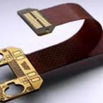
Particularly useful for highly advanced audio, video and data transmission products, Elec & Eltek’s MD-R0124F Filter Connectors are ideal alternatives to standard USB 2.0 Type A connectors where better ESD protection (complying with IEC61000-4-2 specification) and elimination of signal interference is required while ensuring high data speed data transfer of up to 480 MBit/s.
With phosphor bronze contacts and gold plating and shield material made from brass with nickel-plating, the MD-R0124F has an operating temperature range of -40 °C to +85 °C, and is ideal for commercial and industrial USB applications.
“Luso is delighted to make Elec & Eltek’s USB2.0 Filter Connectors more widely available to customers in Europe. ESD protection is a critical component of electronics design given it only takes one ESD strike to permanently damage a product. Electromagnetic interference is another challenge often faced by designers so jacks that can also eliminate noise and maintain signal integrity are also growing in popularity,†explains Andy Eden of Luso Electronics.
The MD-R0124F and a full range of integrated connector modules from Elec & Eltek are available to buy from Luso Electronics for evaluation and qualification.
The "Long High-Speed Transmission FPC" is lightweight and space-saving in comparison to general cables and rigid substrates (*4), while being suitable for high-density wiring and batch connections as well as supporting long-distance, high-speed transmissions. This product is suitable for use in Camera Link cables for imaging devices and USB3.0 cables where demand for faster transmission is constantly increasing; and it also allows for applications in a wide range of fields including sensors and antennas, FA robots and medical fields.
This product will be exhibited at the “JPCA Show 2014” (Booth No.5M-24) which will be held at Tokyo Big Sight from Wednesday 4 - Friday 6 June 2014.
Oki Electric Cable will continue to actively develop new products to accommodate the constantly diversifying customer needs.
FIREFLY™ MICRO FLYOVER SYSTEM™FIREFLY™ MICRO FLYOVER SYSTEM™
Future-proof system easily upgrades from copper to optical using the same connector system. Highest 14 Gbps bandwidth density available.
For furhter information, please feel free to contact us, www.pcbsino.com