Fiber optic connector Flex PCB application
China Flex PCB Manufacturing, Shenzhen Flex PCB Manufacturer, Making Flex Circuit boards
Flex PCB Contract manufacturer, PCB Fabrication, Turnkey assembly services
Buy Flexible Print circuit board, customer: /USA/UK/Canada/South Africa...
Flex PCB Supplier Shenzhen, China, Flex PCB Manufacturer, Turnkey services
-
PCBSINO is the Top 5 PCB manufacturer company in China.
PCBSINO do rapid Flexible PCB Prototype within. we can make Flexible Print circuit boards and Rigid circuit boards, Flex and Rigid Flex PCB, single side, double side, multilayer Flexible print circuit board
PCBSINO making many type electronic product for our customer, Our turkey services team can source original components part for your project(Digikey/Mouser/RS...), senior Electronic engineer will follow each step of the production to solve any PCB problem and our team will do final function test in PCB house.
Flex PCB |
|
Rigid FlexPCB Rapid Prototype |
| Flex PCB |
|
prototype of Flex PCB |
| Flex Prototype |
|
Rigid-Flex PCB Rapid Prototype China, |
Turnkey Services |
|
Turnkey Flex PCB Assembly Services, |
| PCB assembly |
|
Print circuit board Manufacturing, Turnkey assembly |
| PCBA Assembly |
|
SMT Assembly, EMS/OEM supplier China |
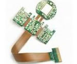
Fiber optic connector Flex PCB application
-
Fiber optic connector Flex PCB application
Molex delivers common fiber optic connectors such as MTP, MPO to MTP/MPO and next-generation MXC with RJ-45 latches alongside revolutionary backplane and FlexPlane options. A leading supplier of fiber optic components,
With an increasing demand for optical backplanes with high-fiber counts and cross-connect systems, Molex FlexPlane™ Optical Flex Circuits provide a versatile, high-density routing solution. Available in virtually any routing scheme, FlexPlane™ fiber provides a variety of design alternatives and facilitates routing from card-to-card or shelf-to-shelf.
Molex 3D FlexPlane™ Optical Backplane Circuits provide a 50% size reduction compared to standard FlexPlane™ circuitry. The 3D option accommodates routing on multiple stacked substrates to achieve a compact routing area.
High-density routing on a flexible, flame-resistant substrate
Compatible with mass and discrete-fiber terminations
Direct or fusion splice termination
Single-mode, multimode, or hybrid
Compatible with MT ferrules
100% insertion loss (IL) and continuity tested
The emergence of faster data rates to keep pace with the demands for data poses a number of technical challenges. While this is not a new or radical thought, the radical conversation on how to combat these challenges—specifically when it comes to the resources, like energy—is imperative to fuel this data deluge. Among the problems that became apparent even at 10 Gbps is the power consumption of copper-interconnect signals within systems—and the problem is compounded at 25 Gbps data rates. Power consumed by the networking equipment alone significantly contributes to the overall energy consumption problem of data centers that is estimated at 30 Billion watts worldwide. 1
The distribution fabric is the major interconnecting part that spans the physical dimensions of the architecture. The functional components add special capabilities to the system such as splitting, combining and filtering of signals. Finally the termination points provide the interface between the fabric and the transceiver components. Here, the main focus will be on distribution and the termination factors. The concept of flexible optics requires complex fabric capable of transporting optical signals between termination points with negligible loss. This solutions also has other physical requirements such as:
1. Low loss distribution.
2. Large size. ( about 30 inches )
3. Compact and flexible.
4. Customised design and fit.
5. Protection of fiber.
6. Management of connections.
7. Low cost.
This article is about idea capture, from the point of view of a board hardware designer. I admit it is a lot of speculations, prototypes were not built, but we have to start somewhere. Signalling speeds over long PCB traces (like backplanes or large boards) can be pushed up to about 28Gbps, while on short ones (close chip-to-chip) up to about 50Gbps. This is what the glass-fibre based cheap-enough PCB material allows, due to losses and fibre weave skew. Today most high-end designs use 10.3Gbit signalling, and transitioning to 28gig in 2013-2015. PAM3 and PAM4 modulations can provide increasing the data bandwidth to another 2x, like it is used in the 100GBASE-KP4 backplane Ethernet. Increasing number of lanes and board/connector density can also provide another 2x-4x advantage at higher cost. These ideas can provide one more generation upgrade to current systems. After this, we don’t have any ready-to-use technologies for increasing interconnect bandwidth. We will have to “go optical” on the board. Looking back to the past, the on-board interconnect speeds were increasing rapidly. For example PCI-express speeds were doubling every four years, today it is 8Gbit (instead of 10Gbps), and so around 2026 it would be 64Gbit/s. Backplane and on-board Ethernet speeds were increasing similarly, 8 times in 11 years from 3.125Gbps XAUI to 25Gbps 100GBASE-KR4. Another 11 years, around in 2025 it would be 200Gbps on each lane. These would definitely need optical connections. When using electrical interconnects on PCBs the practically usable transmission distance is shrinking with increasing signalling speed. The causes are well known within the domain of signal integrity, like losses, reflections, crosstalk, intra-pair skew, mode transformation and inter symbol interference. If we used optical interconnect on the boards, then most of these problems would either go away or would get reduced significantly. Distance vs speed will not be a problem anymore.
COTSWORKS manufactures rugged fiber optic components for the commercial, aerospace, military, and industrial markets and where data communication and sensing is required over fiber optic networking in harsh environments.
COTSWORKS, LLC is a manufacturer of rugged optical components for harsh environments. Founded in 2006, COTSWORKS provides transceivers, cables, and integration services to companies in the commercial aerospace, military, oil and gas, and other industrial markets.
Optical component manufacturer Stratos Lightwave (Chicago, IL) has developed an optical flex-circuit technology that promises to eliminate fiber-optic cable congestion and reduce rack space needed for interconnect points. Designed for higher-density optical applications, the technology consists of individual optical fibers permanently embedded and encapsulated in a flexible substrate, securing each fiber into its correct position.
Optical flex-circuit technology from Stratos Lightwave eliminates fiber-optic cable congestion and reduces rack space needed for interconnect points.
realized by the Gemini Cx, the machine often proves in under a year for annual production runs of only ~400,000 simplex connectors or ~30,000 multifiber MT connectors.
Handles all major simplex and multifiber connector types including: SC, FC, ST, LC, E2K, MT-RJ, as well as, all other MT based connector types
Offers a wide variety of high density batch polishing fixtures
Adaptable to customer-owned fixtures
Handles all varieties and lengths of fiber and cable -- including flex circuits!
Unique roll-to-roll based polishing film dispensing to maximize efficient use of consumables
Auto-sequence from polish to clean to optical inspect utilizing proven process recipes or to user-defined recipes
Enhanced optical surface inspection
Highly developed Graphical User Interface for easy use by any skill level operator
Advanced Statistical Process Control (SPC) and data logging capabilities guarantees end product results
Optical shuffling can be accomplished with various fiber routing and packaging schemes. In one configuration, fibers are ribbonized into 12 sets of 12-fiber arrays, and one fiber from each of the arrays goes to one of the output arrays. The fiber crossovers are housed in a “black box” called the shuffle. A variation of this scheme employs ribbonized fibers entering a sheet of material containing the shuffle routing paths for the fibers. The ribbonized fibers are terminated with optical connectors such as the MPO. This approach is suitable for the variety of multi-fiber connectors available, e.g. MTP, MPX, and other multi-fiber array connectors, as the fibers are ribbonized with 250 um center-to-center spacing. In the assembly process, standard communications-grade optical fiber is laid onto an adhesive substrate material such as Kapton. Following the routing process, a thermoplastic material is laminated over the optical circuit to encapsulate and protect the circuit during handling and environmental extremes.
The company operates out of headquarters in Northeast Ohio with approximately 5,000 square meters of secure and environmentally monitored space. ISO 9001 registered, ATEX-certified, and focused on quality design, manufacture, and customer support, COTSWORKS services the avionics and rugged electronics network communication needs of today and tomorrow.
Our expertise starts with extensive product knowledge in optics for communication: lasers, cables, and connectors. We utilize the best-in-class suppliers to bring their products into our facility where we design and perform final assembly on all of our products. We understand how semiconductor lasers are manufactured and how they operate over time and temperature and connect them with rigid and rigid-ex board designs that can operate over industrial or military temperature specifications. We design our metal housings to perform in noisy environments like aircraft flight decks, mobile ground radar links, and underwater sonar systems. COTSWORKS builds a substantial amount of its own test fixtures and does its own conformal coating which primarily uses Parylene deposition.
Optec's optical fiber flex circuit offers an innovative and flexible solution to precision fiber management that especially suitable for high fiber count backplane applications and cross-connect systems. It provides a manageable means of fiber routing from card-to-card or for the interconnection of optoelectronic devices on the PCB, offering unsurpassed size and weight reduction compared to traditional cable bundles.
kSARIA’s OptiFLEX Fiber Optic Flex Circuits provide for high density routing of fiber optic channels on a flexible substrate for backplanes and systems that require high density optical interconnects.
As bandwidth demands increase, backplanes with higher fiber counts are required. kSARIA’s OptiFLEX Fiber Optic Flex Circuits provide a manageable method of routing fiber from interface to interface and from shelf-to-shelf.
Designed for ultimate flexibility kSARIA’s flex circuit product line provides high-density routing on a flexible substrate.
This fully customizable flex circuit solution consists of a number of optical fibers which are encapsulated in thin protective film substrates, and to pre-terminate with customer specified interconnect interfaces include MT-based connectors (MXC, MTP, MT ferrules), or single-fiber connectors (LC, SC).
FEATURES AND APPLICATIONS
For high fiber count optical backplane applications
- Provide high density fiber routing on a flexible thin film substrates for card-to-card or shelf-to-shelf interconnection
Fully customizable design on configurations
- Diverse substrate size, shape and packaging
The idea is to develop the technology over 3 generations. In the first generation we would use traditional components, electro-optical PCBs and Electro-optical transceiver chips. At later generations the transceiver chips will disappear, making the main processing silicon electro-optical. To develop the technology, cooperation between silicon chip vendors, PCB fabricators, PCB material manufacturers, soldering material manufacturers, PCB assembly services companies and board/system developers.
Currently proposed solutions by Altera, Reflex Photonics, Avago, Zarlink/Microsemi and others include chip-to-cable connections from transceiver modules with inside-box cabling, while the PCB itself is not containing any printed optical waveguides. Compass-EOS has already built a switch chip with a big opening for optical ports on the bottom center of the chip with unknown connectivity and a router system/chassis with it.
Delphi Fiber Optic Cable Assembly (DFOCA) / MIL-PRF-83526 Connectors are next-generation hermaphroditic fiber optic connectors… more
Delphi Flight Termini / MIL-PRF-29504/4 & /5
Delphi's Flight Termini / MIL-PRF-29504/4 & /5 Style contain self-aligning termini which are are the foundation of Delphi's… more
Delphi Flight Termini / MIL-PRF-29504/4 & /5
Delphi's Flight Termini / MIL-PRF-29504/4 & /5 Style contain self-aligning termini which are are the foundation of Delphi's… more
The circuit must distribute optical signals over a distance of at least one standard shelf width without much loss. The need to bridge gap and attach to boards suggested the need of an add on structure that could mount and exist alongside typical hardware. A rugged and flexible circuit is attractive because it may be attached in a variety of ways to panels, using thin tabs that bend and twist the optical leads into connectors. Constraint on the length of an optical fiber lead is reduced because of this flexibility. A physically engineeered circuit also provides the necessary protection by avoiding undue kinking, crushing and macro bending that could result during the system installation and use. The biggest advantage of this circuit approach is that of the compactness obtained when using array or multi-fiber termination. The emerging array technologies can greatly reduce the space required for optical termination. Due to this, the circuit capabilities are even more advantageous in providing break out and cross connect functions. Finally, the optical fabric must be of low cost. This is achieved through the use of design and automation methods suited for the handling fragile glass. The method used to design this is further illustrated in the next section.
The energy use of data centers is already staggeringly large and estimated to be more than 2% of total U.S. electricity consumption. Networking equipment consumes about 50% of a typical data center’s energy. Air movement and cooling equipment consume about 37%, transformers and uninterruptible power supplies account for 10% and lighting and other items take another 3%.2
The U.S. Department of Energy recognized the impact of massive data processing and storage many years ago. In addition to the recently updated Version 2.0 ENERGY STAR specification for Computer Servers that took effect on December 16, 2013, Version 1.0 ENERGY STAR specification for Data Center Storage was also finalized and took effect on December 2, 2013. Purchasing ENERGY STAR rated equipment should significantly lower a data center’s energy consumption and improve the bottom line by reducing energy costs. Acquiring an ENERGY STAR rating should help server and storage equipment suppliers differentiate and increase the sales of their products. More efficient data transmission can play a role in obtaining the ENERGY STAR rating.
Concerns for higher efficiency in data centers go beyond government organizations. For example, the Open Compute Project initiated by Facebook targets greater efficiency in servers and data centers. This type of industry interest places even further demands on more-efficient data communications that can benefit from the use of fiber optic technology. For high-speed communication beyond the first few meters, optics is a field-proven, energy efficient transport mechanism. Figure 1 shows the relative energy efficiency of optical and electrical links.
With core networking doubling every 18 months or so and server I/O density doubling approximately every 24 months (source: IEEE802.org), delaying the inevitable transition to higher-speed data transmission capability could prove costly for many companies.
Molex also offers bulkhead fiber optic connectors, low-loss optical connectors, active optical cable assemblies and plastic optical fiber (POF) cables for a broad range of data transmission solutions. Molex leverages superior density and performance while employing new fiber optic technology to help system architects overcome the challenges of high-speed networking and storage applications ideal for data center – open computing.
MXC* Optical Interconnect Solutions
Features
Ferrule: Expanded-Beam MT
Latch Style: RJ-45
Fiber Count: 64 per ferrule
MTP*/MPO Cable Assemblies and Adapters
Features
Push-pull connector housing
Precision molded NTT compatible ferrule
Shuttered die cast adapters
FlexPlane™ Optical Flex Circuits provide versatile, high-density routing on a flexible substrate for high-fiber-count optical backplanes and cross-connect systems
For furhter information, please feel free to contact us, www.pcbsino.com