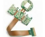
printer Flex PCB application
China Flex PCB Manufacturing, Shenzhen Flex PCB Manufacturer, Making Flex Circuit boards
Flex PCB Contract manufacturer, PCB Fabrication, Turnkey assembly services
Buy Flexible Print circuit board, customer: /USA/UK/Canada/South Africa...
Flex PCB Supplier Shenzhen, China, Flex PCB Manufacturer, Turnkey services
-
PCBSINO is the Top 5 PCB manufacturer company in China.
PCBSINO do rapid Flexible PCB Prototype within. we can make Flexible Print circuit boards and Rigid circuit boards, Flex and Rigid Flex PCB, single side, double side, multilayer Flexible print circuit board
PCBSINO making many type electronic product for our customer, Our turkey services team can source original components part for your project(Digikey/Mouser/RS...), senior Electronic engineer will follow each step of the production to solve any PCB problem and our team will do final function test in PCB house.
Flex PCB |
|
Rigid FlexPCB Rapid Prototype |
| Flex PCB |
|
prototype of Flex PCB |
| Flex Prototype |
|
Rigid-Flex PCB Rapid Prototype China, |
Turnkey Services |
|
Turnkey Flex PCB Assembly Services, |
| PCB assembly |
|
Print circuit board Manufacturing, Turnkey assembly |
| PCBA Assembly |
|
SMT Assembly, EMS/OEM supplier China |
printer Flex PCB application
-
printer Flex PCB application
Flexibility during Installation – Flexible Circuits allow a third dimension to work with because they can interconnect between two or more planes during execution. As a result, they solve space and weight problems unmatched by rigid boards. Flex circuits can be manipulated many times during installation and execution without electronic failure.
High Density Applications – Flexible circuits allow for minutely narrow lines giving way to high density device population. Denser device populations and lighter conductors can be designed into a product, freeing space for additional product features.
Improved Airflow – Because of their streamlined design, flex circuits allow for the flow of cooling air through an electronic application.
*Product Description
Material: Copper,PI,PET,FR4
Copper thickness: 12um-105um
Layer count: 1-8layer
Max panel size: 250*1200mm
Finished board Thickness: 0.05mm-0.3mm(1-2layer),0.15mm-2mm(multi-layer)
Board Thickness Tolerance: 0.02mm-0.2mm
Min hole size: 0.1mm
NPTH hole size tolerance: ±0.05mm
PHT hole size tolerance: ±0.075mm
Min line width: 0.05mm
Min line space: 0.05mm
Solder mask color: black,white,yellow,red,blue,green,lightgreen
Silkscreen color: black,white,yellow,red,blue,green
Outline: Cutting or laser routing
min outline tolerance: ±0.05mm
Surface finish: OSP,Immersion gold,plating gold,Immersion silver
Gold finish thickness: 0.03um-0.75um
E-TEST: Fly-probe,fixture
Oct. 31, 2014 | By Alec
3D printing has been making circuit board manufacturing far easier and cheaper in recent years. Just a few months ago, we even reported on the intriguing portable Squink circuit board 3D printer. However, flexible circuit boards, that are perfect for small and unusual projects, remain very expensive.
All that could change, however, thanks to a cool project by Instructables user Mikey77. He has recently posted a guide for 3D printing circuit boards with just about any type of FDM printer. His handy tutorial could very well hold the key to easy and affordable circuit boards for any project you've been itching to do.
His secret? Ninjaflex Thermoplastic Elastomer (TPE) filament, an FDM 3D printer filament that has an interesting property: it sticks to copper. As Mikey explained, commonly-used filaments like PLA, Nylon and ABS 'do not stick to copper well enough to lay down a pattern that can be etched to create a circuit board.' But this TPE stuff, printed onto a copper substrate, is perfect for making circuit boards in your own home with your own printer.
Firstly, obviously, is design. Mikey relied on the free and popular 123D Design. It was drawn and then extruded to .011" thick. Crucially, he also added a spacer bar to the side of the pattern, which the extrusion head will reach first. 'When it is printed it prints the spacer bar first on the base and then jumps to the circuit board material and starts printing at the right height to accommodate the thickness of the circuit board material.
While working with Ninjaflex filament, you will need to fine tune your 3D printer a bit. This will likely depend on the printer you have, though you will not need a heated bed for this project.
Mikey used an older model of the Replicator 2, which required an extrusion head update. As for other printers, he advises the following: 'If you have a different 3d printer, you should check out Thingiverse for drive blocks that use a spring and roller bearing that will fit your printer. There should be a very small gap (orange arrow) below the bearing and drive gear and the hole where it goes into the hot end of the extruder. Ninjaflex is like a wet noodle and an excessive gap here will allow it to flex and jam.'
Rigid flexible[edit]
Example of Rigid Flex (far left hand side)
Rigid flexible circuits can have circuit boards both externally or internally. They consist of multiple inner layers of flexible circuits. Advantages in rigid flexible circuits include high reliability and flexibility in design options.[1] Rigid flexible circuits contain more materials than flat flexible circuits. The materials include rolled annealed copper, electro deposited copper, epoxy, acrylic, pre-preg, pressure sensitive, adhesiveless base material, FR-4, polyimide, polyester, solder mask, flexible solder mask, and photo image-able cover lay.[2] Rigid flexible circuits are found in electronic products in many areas, such as, in the military and the medical field.[3]
Factory OEM Cheap Rigid Flex PCB/PCBA for 3D printer kit
US $0.1-50 / Piece
1 Piece (Min. Order)
Shenzhen Kingsheng Pcba Tech. Co., Ltd.
BotFactory brings the future of electronic circuit fabrication to your desktop with the introduction of Squink.
Just like a 3D Printer, our small circuit printer allows you to prototype in minutes instead of weeks, all at the click of a button. After pulling Squink from the box, you are guided through a seamless process that will take you from a bare substrate to a fully assembled and functional circuit board in a matter of minutes.
Squink prints on different substrates allowing you to create multilayered rigid and flexible circuits.
Squink dispenses glues and solder pastes as well as pick-and-place components so you may assemble PCBs at your desktop.
Learn more
Nail Polish Resist
For putting resist on the FlecTron (pic 6) or VeilSheild, I painted on clear nail polish. If you put it on thick enough, it will saturate the fabric and resist the etchant on both sides. To keep it from sticking, I painted it on a flat surface with wax paper underneath the fabric. After about 5 minutes it should be dry enough to flip over and touch up any dry spots on the back side.
Draw A Circuit With Crayons As The Resist
See pic 7. It turns out that you can simply draw your circuit pattern on either the FlecTron or Nickel Mesh fabric with crayons. The wax in the crayons is water resistant enough, that even though coverage is not 100 per cent, it works extremely well. The nickel fabric works best with crayons as it is stiffer and fairly transparent. You can place it like tracing paper, over a pencil drawing or printout of your circuit pattern and then draw on it. The traces should be 3/16" or wider. After you have solidly drawn on one side, flip it over and draw in the back side. It must be coated with crayon on both sides to resist the etchant well.
pcb adult flash game flexible pcb manufacture
US $0-60 / Square Meter
1 Piece (Min. Order)
Wells Electronic Technology Ltd.
Polyimide Keypad FPC Flexible PCB with Copper Cover
US $1-10 / Piece
1 Piece (Min. Order)
Shenzhen Futian Xinda Electronic Sales Department
Short time delivery great quality updated cheapest printer pcb
US $1-200 / Piece
100 Pieces (Min. Order)
Tech-Etch manufactures high reliability Flex and Rigid-Flex circuits on most substrates using advanced manufacturing process. We specialize in single and double-sided flex circuits as well as multilayer flex and rigid-flex circuits and also provide SMT component assembly on these products.
The flex circuits are built to the exacting specifications of our customers, meeting the most demanding of applications in the ultrasound probe, medical device, semiconductor test & manufacturing equipment, industrial equipment, and aerospace markets.
With all engineering, tooling, and manufacturing operations housed in our state of the art 150,000 sq. ft. facility in Plymouth, MA, Tech-Etch is the perfect choice for all of your flexible circuit needs, from quick turn and prototype through production volumes.
Flat flexible[edit]
Example of a simple flexible printed circuit.
Flat flexible circuits are able to fold into nearly any shape due to their flexibility and smaller size. Although they are small and light-weight, they are durable and capable of handling high density.[4] Materials in flat flexible circuits include bare copper, tin-plated copper, acrylic, pressure sensitive adhesives, polyester, photoinduced electron transfer, polyethylene naphthalate, tin, conductive silver ink, and aluminum or copper tape.[5] Typical applications of flat flexible circuits include plotters, copiers, and printers.[6]
Advantages[edit]
There are many advantages that come with using flexible circuit technology. Cost related advantages include greater reliability and quicker assembly time. There are also performance advantages, such as, dynamic flexing and increased heat dissipation. Other advantages with using flexible circuits include less weight, increased package density, and a more integrated design.
However, one thing is true for all types of FDM 3D printer and this material: make sure your bed is level! 'There is a very small margin of error for printing a thin coating on copper. To close and the extruder will clog, too far, and it will not stick well enough to etch. Your bed has to be very flat and very, very level. Nothing else will do.'
This can be achieved using calibration.stl to fine tune the levelling of the bed. Print it onto the middle of the bed in PLA. Measure all the ends and make sure they are within .002" of each other in thickness. 'Do not skip this step.'
Then there's just one more step before printing can begin: stick your flexible board material (which can be a thin copper clad board or plated conductive fabric) onto the print bed using an adhesive spray. This is necessary because it needs to be dead flat on the print bed.
Now you can start printing; if the Ninjaflex smears around a bit, you will have to adjust the STL file to thicken the spacer bar. And if it doesn't adhere properly, do the opposite.
Still working with PCBs in 2D? Not [Yoav]. With some clever twists on the way we fab PCBs, he’s managed to create a state-aware foldable circuit board that responds to different configurations.
From his paper [PDF warning], [Yoav] discusses two techniques for developing foldable circuits that may be used repeatedly. The first method involves printing the circuit onto a flexible circuit board material and then bound front-and-back between two sheets of acrylic. Valid folded edges are distinguished by the edges of individual acrylic pieces. The second method involves laying out circuits manually via conductive copper tape and then exposing pads to determine an open or closed state.
Reconfigurable foldable objects may open the door for many creative avenues; in the video (after the break), [Yoav] demonstrates the project’s state-awareness with a simple onscreen rendering that echoes its physical counterpart.
While these circuits are fabbed from a custom solution, not FR1 or FR4, don’t let that note hold your imagination back. In fact, If you’re interested with using PCB FR4 as a structural element, check out [Voja’s] comprehensive guide on the subject.
Quality assurance
Our quality assurance department is the customer’s advocate,
a fully independent body that reports directly to the top managerment .
The QA team always do inspection 100% full check,we implement AQL
standard quality control system.All of products are allowed to deliver to
customer after QA approval.
& Maintenance, compliance and upgrade of QMS
& Maintenance and upgrade of UL certifications
& MRB authority
& Final and in-process inspection
& Internal auditing
& Calibration of tools and measuring equipment
& PPM target:
Fused depositing modeling (FDM) is a fast, efficient process among 3D printing techniques. In this paper, we report the fabrication of the 3D printed flexible circuits based on graphene. Modified two-step in-situ reduced method is used to synthesize reduced graphene oxide (r-GO), whose conductivity can reach to 600 S/cm. Polylactic acid (PLA) and r-GO are mixed by melt blending. The SEM images show that the r-GO can be homogenous dispersed in the PLA. The 3D print-used composites filaments with the diameter of 1.75 mm are fabricated through melt extrusion. The conductivity of the composite filaments from 3D printer can reach to 4.76 S/cm (6 wt% r-GO). The orientation of r-GO occurs during the extrusion process, which contributing to increase the conductivity of the filaments. The composite also exhibit superior mechanical property. The printed 2D and 3D flexible circuits have strong interface bonding force between the layers. The filaments from 3D printer can replace the copper wire because of the high conductivity. This arbitrary 3D graphene-based structure printing technic may open a new prospect in electronic and energy storage fields.
Graphical abstract
High conductive graphene flexible circuits are printed through 3D printing. PLA are chosen as the substrate of graphene. Graphene can be homodispersed in the PLA substrate.
Increased Heat Dissipation – Due to the larger surface-to-volume ratio and compact design of flexible circuits, a shorter thermal path is allowed. Further, the thinner design of flex circuits allows for heat dissipation from both sides of the circuit.
Increased System Reliability – In the past, most circuit failures occurred at an interconnection point. Flex circuits can be designed so that interconnections are reduced, which in turn, increases the reliability of a circuit.
Finally, the conductive material you've known you wanted but never knew you could have, its a sheet of flex PCB material! This is the stuff used to make flexible circuits, but raw and unetched. You can treat it just like 1 oz copper clad, etch it with ferric chloride (or other PCB etching systems) or cut with scissors. It may even be possible to laser or CNC engrave (we haven't tried it ourselves but we'd love to hear about it if you get any results.)
Pyralux is the brand name of Dupont's flex PCB material that's used in cell phones and other small circuits. One side of it's 1 oz copper while the other side is polyamide for strength and flexibility. The material can be manipulated through and around small areas and won't crack as easily as copper tape. Pyralux is used in a ton of consumer-grade electronics and one of the reasons why things like your cell phones have advanced from bulky and cumbersome to miniature super computers.
Comes with a 6"x6" (152mm x 152mm) square of Pyralux. It's ED-Y type copper at 35um (1 oz/ft2) and has a polymide of 25um (1 mil). The thick copper layer means it can carry a lot of current, and its trivial to solder to it. We have a little demo of it with a 1W LED above.
All of this makes Pyralux yet another great material for your next wearables project or whatever project you come up with!
Point-to-Point Wire Replacement – Depending on the number of point-to-point connections in a circuit design, at Flexible Circuit, we guarantee that we can design and build a single flex circuit that can eliminate many (if not all) of those interconnections. At Flexible Circuit, “We Go Where Others Will Not.”
Reliability and Durability – A flexible circuit can move and flex up to 500 million times without a failure, in designs that have moving parts. The exceptional thermal stability of polyimide also allows the circuit to withstand applications with extreme heat. The thermal stability of polyimide provides a better base for surface mounting than hard boards. Because the compliant base film places less stress on soldered joints, a thermal mismatch is less likely to occur.
Repeatable Routings – Our circuits are made from precise replicas of artwork for superior manufacturing consistency. The etched circuits replace the solder and hand wiring connections of the rigid board, completely eliminating wiring errors.
Simplified Circuit Geometry – Flexible Circuit Technologies places surface mount electronics directly onto the circuit which results in streamlining the overall design. Intricate patterns that were nearly impossible to achieve with rigid boards are made easily in flex circuits.
For furhter information, please feel free to contact us, www.pcbsino.com