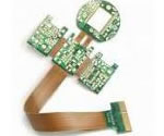
Acceleration sensor Flex PCB application
China Flex PCB Manufacturing, Shenzhen Flex PCB Manufacturer, Making Flex Circuit boards
Flex PCB Contract manufacturer, PCB Fabrication, Turnkey assembly services
Buy Flexible Print circuit board, customer: /USA/UK/Canada/South Africa...
Flex PCB Supplier Shenzhen, China, Flex PCB Manufacturer, Turnkey services
-
PCBSINO is the Top 5 PCB manufacturer company in China.
PCBSINO do rapid Flexible PCB Prototype within. we can make Flexible Print circuit boards and Rigid circuit boards, Flex and Rigid Flex PCB, single side, double side, multilayer Flexible print circuit board
PCBSINO making many type electronic product for our customer, Our turkey services team can source original components part for your project(Digikey/Mouser/RS...), senior Electronic engineer will follow each step of the production to solve any PCB problem and our team will do final function test in PCB house.
Flex PCB |
|
Rigid FlexPCB Rapid Prototype |
| Flex PCB |
|
prototype of Flex PCB |
| Flex Prototype |
|
Rigid-Flex PCB Rapid Prototype China, |
Turnkey Services |
|
Turnkey Flex PCB Assembly Services, |
| PCB assembly |
|
Print circuit board Manufacturing, Turnkey assembly |
| PCBA Assembly |
|
SMT Assembly, EMS/OEM supplier China |
Acceleration sensor Flex PCB application
-
Acceleration sensor Flex PCB application
The tendency of polymers to absorb moisture impairs especially their electrical and mechanical properties. These are important characteristics for printed circuit board (PCB) materials, which should provide mechanical support as well as electrical insulation in many different environments in order to guarantee safe operation for electrical devices. Moreover, the effects of moisture are accelerated at increased temperatures. In this study, three flexible PCB dielectric materials, namely polyimide (PI), fluorinated ethylene-propylene (FEP), and polyethylene terephthalate (PET), were aged over different periods of time in a high-humidity test, in which the temperature was 85°C and relative humidity 85%. After aging, the changes in the structure of the polymers were studied by determining different material parameters such as modulus of elasticity, glass-transition temperature, melting point, coefficient of thermal expansion, water absorption, and crystallinity, and changes in the chemical structure with several techniques including thermomechanical analysis, differential scanning calorimetry, Fourier-transform infrared spectroscopy, moisture analysis, and a precision scale. The results showed that PI was extremely stable under the aging conditions and therefore an excellent choice for electrical applications under harsh conditions. Similarly, FEP proved to be relatively stable under the applied aging conditions. However, its crystallinity increased markedly during aging, and after 6000 h of aging the results indicated oxidation. PET suffered from hydrolysis during the test, leading to its embrittlement after 2000 h of aging.
Version 1: Manufactured PCB
Introduction to acceleration sensors
I am working on my final year project which involves the use of the Nitendo Wii Nunchuk. The Wii Nunchuk operates based on a 3-axis accelerometer, a joystick and two push buttons. I carried out a small theoretical research on the accelerometer, and in this wiki page I am going to briefly explain what an accelerometer is, how it works, types of accelerometers, characteristics of accelerometers, how to select an accelerometer for a project requirement, and shows some applications of accelerometers.
Physically, acceleration is a vector quantity having both direction and magnitude that is defined as the rate at which an object changes its velocity with respect to time. It is a measure of how fast speed changes . An object is accelerating when its velocity is changing. [1. ] In order to measure acceleration, an acceleration sensor called accelerometer is used. Accelerometer measures in units of g. A g is the acceleration measurement for gravity which is equal to 9.81 m/s². However, depending on altitude, this measurement can be 10 m/s² in some place.
Working principle of an accelerometer
The design of an accelerometer is based on the application of physics phenomenon. In aviation, accelerometers are based on the properties of rotating masses. In the world of industry, however, the design is based on a combination of Newton's law of mass acceleration and Hooke's law of spring action. This is the most common design applied to the making of accelerometers, and therefore, in this wiki page I will focus on explaining the accelerometer's working principle based on this combination of Newton's law and Hooke's law. Figure 1 shows a simplified spring-mass system. In figure 1a, the mass of mass m is attached to a spring at equilibrium position x0 which in turn is attached to the base. The mass can slide freely on the base. Suppose that the base friction is negligible. Figure 1b shows the mass is moving to the right by a displacement of Δx = x - x0. Since the mass is slowing down, the direction of acceleration vector is to the left. In this case, the mass is subject to the force according Newton's second law and Hooke's law.
Summary of design: Surface-mount low-profile male headers for x-OSC connection with the following pins broken out:
– GND and VCC (3.3V)
– 10 input pins broken out to snap pads (with pull-up resistors)
– 6 input pins broken out to pads for additional sensors (with pull-up resistors)
– 3 output pins broken out to RGB led (with resistors)
– 2 output pins broken out to left and right vibration motor
– 11 output pins left unconnected
USB micro plug connected to power x-OSC (USB mini location conflicted with JST from x-OSC).
Two additional small flex PCBs for vibration motors.
Power supplier using flexible PCB based on self-powering and sensor node using the same
US 8664833 B2
ABSTRACT
Disclosed are a slim self-powering power supplier using a flexible PCB for a wireless sensor network and a sensor node using the same, and a fabrication method thereof. An exemplary embodiment of the present disclosure provides a self-powering power supplier including: a flexible PCB; a lower electrode positioned on the flexible PCB; a piezoelectric body having a cantilever structure deposited on the lower electrode; and an upper electrode formed on the piezoelectric body.
IMAGES(12)
Keywords: General Purpose Industrial Grade Accelerometers acceleration sensor 1 axis accelerometer, 3 pole terminal block load cell weight mechanical timers usb data acquisition board
Next page
CLAIMS(17)
What is claimed is:
1. A self-powering power supplier, comprising:
a flexible PCB;
a lower electrode positioned on the flexible PCB;
a piezoelectric body having a cantilever structure deposited on the lower electrode; and
an upper electrode formed on the piezoelectric body.
2. The self-powering power supplier of claim 1, wherein the lower electrode is minutely patterned by using photolithography and etched by wet etching.
3. The self-powering power supplier of claim 1, wherein the upper electrode is patterned by using a stencil mask.
4. The self-powering power supplier of claim 1, wherein the piezoelectric body is deposited on the lower electrode by using the stencil mask or screen printing.
5. The self-powering power supplier of claim 1, wherein mass bodies are attached to the center and edges of the piezoelectric body.
6. The self-powering power supplier of claim 5, wherein a plurality of resonance points are formed by attaching mass bodies having different sizes or different masses to the edges of the piezoelectric body.
7. The self-powering power supplier of claim 1, wherein the piezoelectric body has a plurality of cantilever structures serving as a torsion bar.
8. The self-powering power supplier of claim 1, wherein electronic circuit components required for controlling a power supplying element is soldered to be formed on the PCB.
9. The self-powering power supplier of claim 1, wherein the self-powering power supplier is attached to a vibration generating device and generates electricity by vibration generated by the vibration generating device.
10. The self-powering power supplier of claim 1, further comprising a rectifier and a voltage regulator.
11. A self-powering sensor node, comprising:
a flexible PCB;
a lower electrode positioned on the flexible PCB;
a piezoelectric body having a cantilever structure deposited on the lower electrode;
an upper electrode formed on the piezoelectric body; and
a sensor using electricity collected by the upper electrode and the lower electrode as a power.
12. The self-powering sensor node of claim 11, further comprising an LED using the electricity collected by the upper electrode and the lower electrode as a power.
13. The self-powering sensor node of claim 11, wherein the sensor is a tire pressure monitoring system (TPMS) sensor.
14. The self-powering sensor node of claim 11, wherein the sensor includes at least one of temperature, humidity, gas, and wind speed sensors.
15. The self-powering sensor node of claim 11, further comprising an antenna for transmitting a value measured by the sensor wirelessly.
16. A method of fabricating a self-powering power supplier, comprising:
forming a lower electrode having a cantilever structure on a flexible PCB;
depositing a piezoelectric body on the lower electrode; and
forming an upper electrode on the piezoelectric body.
17. A method of fabricating a self-powering power supplier, comprising:
fabricating a piezoelectric element by forming a lower electrode having a cantilever structure, depositing a piezoelectric body on the lower electrode, and forming an upper electrode on the piezoelectric body; and
mounting the piezoelectric element on a flexible PCB with electronic circuit components.
Automotive Capacitive Acceleration Sensing: CAS
Acceleration sensors reliably monitor acceleration of parts in plants or machinery. Due to the two-piece mounting concept, F99 series acceleration sensors from Pepperl+Fuchs are extremely robust and also suited for harsh outdoor conditions. Thus, they are typically used in wind turbine installations and large machinery, where they monitor set vibration limits, in elevators, or in large plants.. Measuring range and outputs can be configured individually according to the specific application requirements.
For reliable acceleration monitoring in dynamic applications, the F99-Fusion is an ideal solution. The inertial measurement unit allows a customized parameterization of measuring ranges and outputs, so users are provided with the data they want to monitor. In addition, the F99-Fusion can fade out certain accelerations, in order to only monitor vibration.
•
Highly reliable sensor design proven with years of production experience
•
Qualified for underhood, chassis mount, or automotive interior
•
1g, 2g, and 10g full–scale options available
•
Permanent calibration after assembly
•
Low–cost
•
Operating range: -40°C to 85°C
•
Sensitivity up to 3 V/g; output rationmetric with supply
•
Flat response DC to 50Hz (-3dB)
•
Total error band ±5% Full Scale (includes calibration, linearity, thermal offset, and drift-over-life)
•
EMC: radiated suspectibility 200V/m up to 500MHz
•
Automotive fluid compatibility
•
We are QS9000 certified, delivering <50ppm AIQ
CAS meets the demanding expectations of the automotive industry.
Sensors & Controls CAS is a capacitive–based sensor that provides a linear output voltage directly proportional to acceleration input. Integral signal conditioning electronics incorporate a custom designed integrated circuit and provide an accurate, stable signal over a wide operating temperature range (-40° to 85°C).
DESCRIPTION
CROSS-REFERENCE TO RELATED APPLICATIONS
This application is based on and claims priority from Korean Patent Application No. 10-2010-0129038, filed on Dec. 16, 2010, with the Korean Intellectual Property Office, the present disclosure of which is incorporated herein in its entirety by reference.
TECHNICAL FIELD
The present disclosure relates to a slim self-powering power supplier using a flexible PCB for a wireless sensor network and a sensor node using the same, and a fabrication method thereof.
More particularly, the present disclosure a method of fabricating a slim self-powering small-sized piezoelectric generator system by depositing a piezoelectric material by forming a thin metallic plate or a lower electrode of a piezoelectric generating element by a deposition method on a thin and light flexible PCB and soldering other electronic circuit components, and a method of designing and fabricating a power supplier and a sensor node of a wireless sensor network by using the fabricated elements under an environment with vibration or wind and an apparatus using the same.
BACKGROUND
Systems that support a driver to perform safe driving and rapidly perform emergency measures in emergency by providing to the driver information on air pressure in a tire while travelling through diagnosis of a tire condition like a tire pressure monitoring system (TPMS) of a vehicle have been developed to provide a function for acquiring sensor information of various wireless sensor networks in addition to the TPMS. However, since supply power is used up depending on the use of a secondary battery and thereafter, a need for battery replacement through manpower allocation, troublousness and temporal and economical losses are generated at all times. Further, it is very important to select a light element due to problems caused by deposition of piezoelectric materials and an increase in volume in order to improve an output of a piezoelectric power generating element.
WHEN TO USE FLEX CIRCUIT VS. RIGID CIRCUIT BOARDS
Piezoelectric sensing of acceleration is natural, as acceleration is directly proportional to force. When certain types of crystal are compressed, charges of opposite polarity accumulate on opposite sides of the crystal. This is known as the piezoelectric effect. In a piezoelectric accelerometer, charge accumulates on the crystal and is translated and amplified into either an output current or voltage.
Piezoelectric accelerometers only respond to AC phenomenon such as vibration or shock. They have a wide dynamic range, but can be expensive depending on their quality (Doscher 2005)
Piezo-film based accelerometers are best used to measure AC phenomenon such as vibration or shock, rather than DC phenomenon such as the acceleration of gravity. They are inexpensive, and respond to other phenomenon such as temperature, sound, and pressure (Doscher 2005)
Overview of other types that are less used in audio applications
Piezoresistive
Piezoresistive accelerometers (also known as Strain gauge accelerometers) work by measuring the electrical resistance of a material when mechanical stress is applied. They are preferred in high shock applications and they can measure acceleration down to 0Hz. However, they have a limited high frequency response.
Rigid circuit boards tend to form the backbone of most innovative new products. However, innovation can sometimes be sacrificed to available space because manufacturers increasingly want to make their devices smaller and smaller. This points to an increasing trend towards using flexible circuits for a wide variety of applications.
No Compromise Between Power and Volume
Medical devices and implants.
Inner-engine automobile sensors.
Measurement sensors for the oil and gas industry.
Consumer electronics.
Flexible circuitry may be preferable to rigid circuitry in situations where space or weight is limited.
Size and Weight Reduction Benefits to Flexible Circuitry
Generally, flexible circuitry is the go-to solution for manufacturers who need:
Wiring solutions that fit where rigid boards cannot.
Thin, lightweight products that are nonetheless durable.
Miniaturized versions of existing technologies.
Three-dimensional packaging geometry.
A low number of device interconnects.
Shock and vibration resistance.
These benefits point to flexible circuitry options as an ideal solution for mobile consumer electronics. Enterprising circuit board amateurs who take apart their smartphones or laptop computers will find a wealth of flexible circuitry inside any modern device on the market.
In the case of mobile devices, the use of rigid circuitry would result in a device too large, too heavy, and too fragile to conveniently carry around. This was the case with the Osborne I, the first fully powered mobile computer, which weighed in at an intimidating 24.5 pounds.
Size and weight reduction represent only one half of the flexible circuit story, however. They are also ideal for high temperature and high-density applications.
As seen in the example of the TPMS, the development of a system which a TPMS module installed in an aluminum wheel in the tire can transmit and receive a target to be determined, that is, information on a space to and from has been extremely required. In addition, in configuring the wireless sensor network, sensor components have been light-weight and small-sized due to the development of MEMS elements that take charge of several functions and as the piezoelectric power generating element that is developed as a substitution for the secondary battery,
Populated boards:
Unpopulated boards bottom (left) and top (right) views:
Copper layers (top=red, bottom=blue):
Minco Products Circuits
Share:
Circuits
As markets trend toward miniaturization, customers rely on Minco’s broad Flexible Printed Circuit (FPC) design capabilities when flexibility is required for tight, small spaces. Our flex circuits offer the same advantages of Printed Circuit Board (PCB) including repeatability, reliability and high density but with the added twist of flexibility and vibration resistance.
Manufacturers use flex circuits for their superior reliability and ability to condense their electronic package size. A flex circuit offers a customizable and repeatable routing path in a thin package. The materials used are robust enough to withstand high vibration, resist abrasion, and endure thousands to millions of flexing cycles.
Perhaps the most important attribute customers prefer in choosing flex circuit technology is the capability of the flex circuit to assume three-dimensional configurations: they can be shaped to fit where no other design can and offer unlimited freedom of packaging geometry while retaining density and repeatability of printed circuits.
Connections (green=inputs, brown=outputs):
PCB Piezotronics manufactures precision accelerometers to measure vibration, shock, acceleration, and motion for monitoring, control, and testing applications. ICP®, PE, MEMS and Capacitance sensing technologies are used to fulfill a wide assortment of measurement requirements. Accelerometers are used by field test, in factory production and design as well as Research and Development organizations to acquire critical data. In addition to our precision miniature units for Research and Development, rugged accelerometers and vibration sensors are available for industrial machinery health monitoring.
Single axis and three axis (triaxial) accelerometer configuration parameters include sensitivity, temperature, frequency response, amplitude response, form factor and lead wire grounding. Accelerometers are critical for evaluating proper performance of equipment or structures. Such applications usually require proof of calibration of the entire measurement system from the sensor through to the final output. PCB calibrates all products traceable to NIST and includes a calibration certificate with each sensor shipped.
Read More +
Featured Accelerometers:
Accelerometers can be used to measure vehicle acceleration. Accelerometers can be used to measure vibration on cars, machines, buildings, process control systems and safety installations. They can also be used to measure seismic activity, inclination, machine vibration, dynamic distance and speed with or without the influence of gravity. Applications for accelerometers that measure gravity, wherein an accelerometer is specifically configured for use in gravimetry, are called gravimeters.
Notebook computers equipped with accelerometers can contribute to the Quake-Catcher Network (QCN), a BOINC project aimed at scientific research of earthquakes.[6]
Biology[edit]
Accelerometers are also increasingly used in the biological sciences. High frequency recordings of bi-axial[7] or tri-axial acceleration[8] allows the discrimination of behavioral patterns while animals are out of sight. Furthermore, recordings of acceleration allow researchers to quantify the rate at which an animal is expending energy in the wild, by either determination of limb-stroke frequency[9] or measures such as overall dynamic body acceleration[10] Such approaches have mostly been adopted by marine scientists due to an inability to study animals in the wild using visual observations, however an increasing number of terrestrial biologists are adopting similar approaches. This device can be connected to an amplifier to amplify the signal.
NEW Teardrop ICP® Accelerometers ‐
with Flexible, Integral Cable
NEW Miniature Accelerometers –
Small, lightweight, TEDS Enabled
NEW High Shock ICP®
Triaxial Accelerometer
Here are the basic steps to make this prototype (circuit layout & pinouts) :
1. Solder the accelerometer in place
(a) Tape the flex circuit down and the accelerometer to line up with the circuit's solder pads
(b) Tack the accelerometer down at two points
(c) Remove the tape from the accelerometer and solder the rest of the pads (and perhaps retouching the original tacked solder joints).
2. Solder the SMT resistors and capacitors in place
3. Check continuity and sensor outputs
4. Clean off flux/rosin residue
5. Place dielectric tape over traces (front side)
6. Laminate stiffeners onto the back side of the circuit
7. Crimp on flex-circuit connector
8. Double check sensor outputs
9. (Optional) Pot solder joints
An accelerometer is a device that measures proper acceleration.[1] Proper acceleration, being the acceleration (or rate of change of velocity) of a body in its own instantaneous rest frame,[2] is not the same as coordinate acceleration, being the acceleration in a fixed coordinate system. For example, an accelerometer at rest on the surface of the Earth will measure an acceleration due to Earth's gravity, straight upwards (by definition) of g ≈ 9.81 m/s2. By contrast, accelerometers in free fall (falling toward the center of the Earth at a rate of about 9.81 m/s2) will measure zero.
Accelerometers have multiple applications in industry and science. Highly sensitive accelerometers are components of inertial navigation systems for aircraft and missiles. Accelerometers are used to detect and monitor vibration in rotating machinery. Accelerometers are used in tablet computers and digital cameras so that images on screens are always displayed upright. Accelerometers are used in drones for flight stabilisation. Coordinated accelerometers can be used to measure differences in proper acceleration, particularly gravity, over their separation in space; i.e., gradient of the gravitational field. This gravity gradiometry is useful because absolute gravity is a weak effect and depends on local density of the Earth which is quite variable.
Single- and multi-axis models of accelerometer are available to detect magnitude and direction of the proper acceleration, as a vector quantity, and can be used to sense orientation (because direction of weight changes), coordinate acceleration, vibration, shock, and falling in a resistive medium (a case where the proper acceleration changes, since it starts at zero, then increases). Micromachined microelectromechanical systems (MEMS) accelerometers are increasingly present in portable electronic devices and video game controllers, to detect the position of the device or provide for game input.
A detailed description of the wearable shoe-based sensor system can be found in [22] and [23]. Each shoe comprises five FSR sensors (Interlink, Inc.), and a 3-D accelerometer based on MEMS technology (LIS3D02AS). The FSR sensors were located in different foot contact points, the heel, the heads of the metatarsal bones, and the great toe, soldered into a flexible printed circuit board (PCB); these sensors were used to capture variations of pressure in the plantar area at all times (see Fig. 1). The FSR sensors respond approximately linearly to pressure exerted by the feet in different postures (standing, sitting) or activities (walking) [23]. However, the quantitative measure of the pressure is not of interest for this study, but the qualitative measure is. The accelerometer was mounted on the heel at the back of the shoe together with the battery, power switch, and wireless board in a rigid PCB (see Fig. 1). Data were sampled from these sensors at 25 Hz with a 12-bit ADC and sent to a portable computer system using a wireless intelligent sensor and actuator network (WISAN) wireless link [28] and stored on a hard drive. The choice of sampling frequency was made as a design tradeoff between battery life and physical size, both defined by power consumption during sampling and wireless transmission and time resolution of temporal gait parameters. The proposed algorithms should perform equally well for higher sampling frequencies [22]. The combination of these sensors has been successfully used to automatic recognize different postures and activities of stroke patients [23]. In this study, the variations of pressure captured by the FSR sensors were used to detect the temporal gait parameters. The integrated sensors add no significant weight to the shoe (a five-pad sensor insole with connector weighs 17 g) and do not cause observable interference with normal motion, posture, or normal activities. Subjects who participated in the data collection expressed no discomfort or apparent change of walking behavior while wearing the shoe sensors. The wireless sensor system is also inexpensive: the cost of parts per shoe-sensor pair is less than U.S.$ 100 in single quantities and can scale down substantially in mass production. Data obtained from the FSR sensors was used to estimate the following temporal gait parameters: cadence, step time, cycle time, percentage of gait cycle in swing for each lower extremity, percentage of gait cycle in stance for each lower extremity, percentage of gait cycle in single limb support for each lower extremity, and percentage of gait cycle in double limb support for each lower extremity. These temporal gait parameters are most relevant for clinical practice [29], [30] as they provide a method of assessing gait symmetry and serve as an accurate measure of motor recovery after stroke [21]. First, for each subject’s foot the sum of all five FRS sensors was calculated as
For furhter information, please feel free to contact us, www.pcbsino.com